 Hyundai Santa Fe: 4WD ECU. Schematic Diagrams
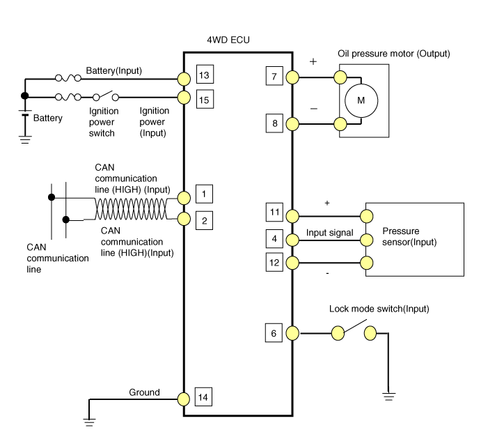
Circuit Diagram
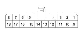
| 4WD ECU Connector |

|
Pin |
Function |
|
1 |
CAN communication line (Low) |
|
2 |
CAN communication line (High) |
|
3 |
- |
|
4 |
Pressure sensor signal(+) |
|
5 |
- |
|
6 |
Lock mode switch |
|
7 |
Oil pressure motor B |
|
8 |
Oil pressure motor A |
|
9 |
- |
|
10 |
- |
|
11 |
Pressure sensor(Input) |
|
12 |
Input sensor signal(-) |
|
13 |
Battery power |
|
14 |
Ground |
|
15 |
IG power |
|
16 |
- |
|
17 |
- |
|
18 |
- |
4WD ECU Circuit Diagram

 4WD ECU. Flow Diagram
Power Flow Diagram 4WD ECU Input&Output Diagram ...
 4WD ECU. Repair procedures
Replacement 1. Prior to replacing the 4WD ECU, check the 4WD ECU's clutch learing with the GDS tool. 2. Disconnect the battery negative cable from the battery 3. Disconnect the 4WD ECU connector (A). ...
See also:
Battery replacement
A smart key battery should last for several years, but if the smart key is not working properly, try replacing the battery with a new one. If you are unsure how to use your smart key or replace the battery, ...
Floor Console Assembly. Components and Components Location
Component Location [Console rear complete assembly] 1. Console rear complete assembly [Console front complete assembly] 1. Console front complete assembly ...
Forward and backward
To move the seat forward or backward: 1. Pull the seat slide adjustment lever up and hold it. 2. Slide the seat to the position you desire. 3. Release the lever and make sure the seat is locked in place. ...
