
 Hyundai Santa Fe: Engine Mounting. Repair procedures
Removal and Installation
Roll road Bracket
| 1. |
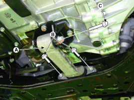
Remove the roll road bracket(A).
|
| 2. |
Install in the reverse order of removal.
|
Engine Mounting Bracket
| 1. |
Install the jack to the edge of upper oil pan to
support the engine.
|

| 2. |
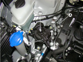
Disconnect the ground cable (A), and then remove
the engine mounting support bracket (B).
|
| 3. |
Remove the reservoir tank.
|
| 4. |
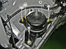
Remove the engine mounting bracket(A).
|
| 5. |
Install in the reverse order of removal.
|
Transaxle Mounting Bracket
| 1. |
Remove the air duct.
|
| 2. |
Remove the battery and tray.
|
| 3. |
Remove the air cleaner assembly.
|
| 4. |
Install the jack to the edge of transaxle.
|
| 5. |
Disconnect the ground cable(A).
|

| 6. |
Remove the service cover(A).
|

| 7. |
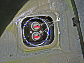
Remove the transaxle mounting bolts(A).
|
| 8. |
Remove the transaxle mounting bracket(A).
|
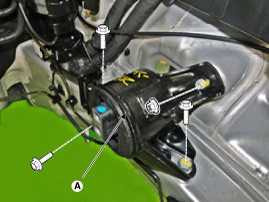
| 9. |
Install in the reverse order of removal.
|
 Engine Mounting. Components and Components
Location
Engine Mounting. Components and Components
Location
Components 1. Transaxle mounting bracket 2. Roll rod bracket 3. Engine mounting bracket 4. Engine mounting support bracket ...
 Repair
procedures
Repair
procedures
Removal • Use fender covers to avoid damaging painted surfaces. • To avoid damage, unplug the wiring connectors carefully while holding the connector portion. • Mark all wiring and hoses to avoid ...
See also:
Components and Components Location
Component Location 1. Fuel filler door ...
Relay Box (Engine Compartment). Repair procedures
Inspection 1. Disconnect the negative (-) battery terminal. 2. Pull out the relay from the engine compartment relay box. Power Relay (Type A) Check for continuity between the terminals. A : Power outlet ...
Highway driving
Tires: Adjust the tire inflation pressures to specification. Low tire inflation pressures will result in overheating and possible failure of the tires. Avoid using worn or damaged tires which may result ...
