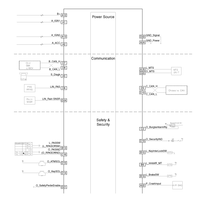
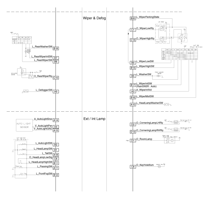
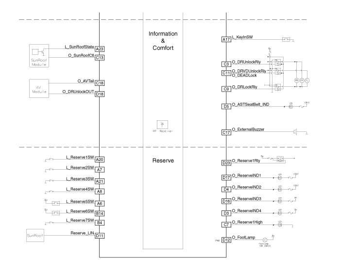
 Hyundai Santa Fe: Schematic Diagrams
Circuit Diagram


 Components and Components
Location
Components Connector Pin Information No. Connector A Connector B Connector C Connector D 1 IGN1 Head lamp low switch Wiper low relay Room lamp 2 ACC Auto light switch Burglar alarm relay Cornering lamp ...
 Description and Operation
Description Body Control Module Controls The Followings - Wiper & Washer Control - Defroster Control - Driving Control - Tailgate Control - Window Control - Interior Control - Exterior Control - Panic ...
See also:
Knock Sensor (KS). Specifications
Specification Item Specification Capacitance (pF) 850 ~ 1,150 ...
Trailer brakes
If your trailer is equipped with a braking system, make sure it conforms to federal and/or local regulations and that it is properly installed and operating correctly. If your trailer weight exceeds the ...
Direct Electro Hydraulic Actuator Coupling. Components and Components Location
Component Location 1. Coupling assembly 2. Propeller shaft 3. Transfer assembly Components 1. Coupling assembly 2. Input shaft 3. Pressure sensor 4. Extension wiring 5. Oil hydraulic Motor(Actuator) ...
