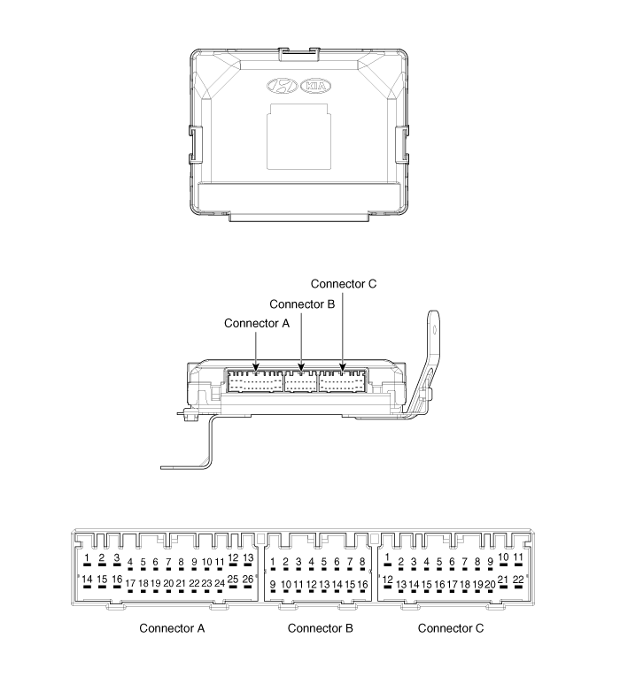
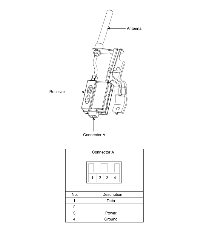
 Hyundai Santa Fe: Smart Key Unit. Components and
Components Location
Components (1)

Connector Pin Information
|
No. |
Connector A |
Connector B |
Connector C |
|
1 |
V_BAT load |
C_CAN Low |
SSB illumination ground |
|
2 |
- |
C_CAN High |
- |
|
3 |
Power ground1 |
- |
SSB LED OFF |
|
4 |
IGN1 |
- |
Interior antenna #2 power |
|
5 |
IGN1 relay |
Brake switch |
Interior antenna #1 power |
|
6 |
ACC |
Immobilizer antenna power |
- |
|
7 |
IGN2 |
- |
- |
|
8 |
SSB switch2 |
Wheel speed |
Interior antenna #3 power |
|
9 |
- |
Driver toggle button |
Bumper antenna power |
|
10 |
RF COM |
- |
Passenger side antenna power |
|
11 |
- |
External buzzer |
Driver side antenna power |
|
12 |
B_CAN High |
P position/ Clutch switch |
SSB LED IGN |
|
13 |
B_CAN Low |
Start feedback |
SSB illumination power |
|
14 |
V_BAT CPU |
Immobilizer antenna ground |
- |
|
15 |
- |
- |
Interior antenna #2 ground |
|
16 |
Power ground2 |
SSB LED ACC |
Interior antenna #1 ground |
|
17 |
Starter relay |
|
- |
|
18 |
IGN2 relay |
- |
|
|
19 |
ACC relay |
Interior antenna #3 power |
|
|
20 |
- |
Bumper antenna ground |
|
|
21 |
- |
Passenger side antenna ground |
|
|
22 |
- |
Driver side antenna ground |
|
|
23 |
RPM |
|
|
|
24 |
EMS COM |
||
|
25 |
SSB switch1 |
||
|
26 |
Assistant toggle button |
Components (2)

 Smart Key. Repair procedures
Smart Key Smart Key Code Saving 1. Connect the DLC cable of GDS to the data link connector (16 pins) in driver side crash pad lower panel, turn the power on GDS. 2. Select the vehicle model and then do ...
 Smart Key Unit. Schematic Diagrams
Circuit Diagram ...
See also:
To remove the cargo security screen
1. Push in the guide pin. 2. While pushing the lever, pull out the cargo security screen. 3. Open the luggage tray and keep the cargo security screen in the tray. ...
Passenger Airbag (PAB) Module. Components and Components Location
Components ...
Audio Remote Control. Components and Components
Location
Components 1. Remote control switch (LH) 2. Remote control switch (RH) 3. Bluetooth hands free switch 4. Trip switch ...
