 Hyundai Santa Fe: TPMS Receiver. Schematic Diagrams
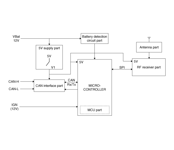
System Circuit Diagram
|
No |
Function |
|
1 |
MCU part |
|
2 |
CAN interface part |
|
3 |
5V supply part |
|
4 |
Battery detection circuit part |
|
5 |
RF receiver part |
|
6 |
Antenna part |
 TPMS Receiver. Description and Operation
Description It search automatically sensor location and learn the new sensor. To check defect of system or vehicle, use the sensor information, distance, indistinct noise, automatic learning status, vehicle ...
 TPMS Receiver. Repair procedures
Adjustment 1. Disconnect the negative (-) battery cable. 2. Remove the glove box housing. 3. Disconnect the connector. 4. Remove the bracket (B) and receiver (C) as loosen the nut (A-1ea). Tightening torque ...
See also:
Do not install a child restraint on the front passengerŌĆÖs seat.
Never place a rear-facing child restraint in the front passengerŌĆÖs seat. If the air bag deploys, it would impact the rear-facing child restraint, causing serious or fatal injury. In addition, do not ...
Power brakes
Your vehicle has power-assisted brakes that adjust automatically through normal usage. In the event that the power-assisted brakes lose power because of a stalled engine or some other reason, you can still ...
Checking the amount of air conditioner refrigerant and compressor lubricant
When the amount of refrigerant is low, the performance of the air conditioning is reduced. Overfilling also has a negative influence on the air conditioning system. Therefore, if abnormal operation is ...
