 Hyundai Santa Fe (TM): Intake And Exhaust System
Air Cleaner. Repair procedures
| Removal and Installation |
Air Cleaner Assembly
| 1. |
Disconnect the battery negative terminal.
|
| 2. |
Remove the engine cover.
(Refer to Engine And Transaxle Assembly - “Engine Cover”)
|
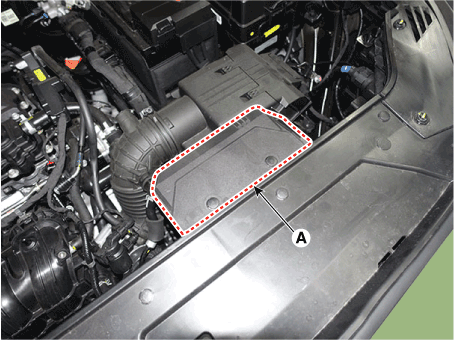
| 3. |
Remove the air duct (A).
|
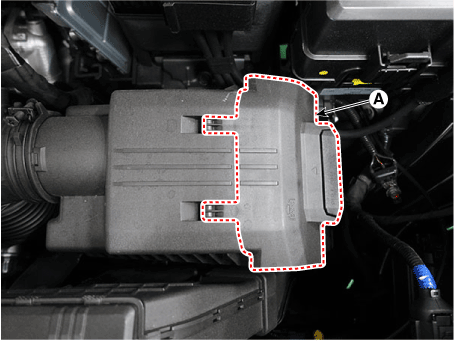
| 4. |
Remove the air cleaner assembly.
|
| 5. |
Install in the reverse order of removal.
|
Air Cleaner Element Replacement
| 1. |
Open the air cleaner element cover (A) by lifting up the air cleaner
element cover handle.
|
| 2. |
Unlock the air cleaner element camshaft (A) by turning in the direction
of arrow.
|
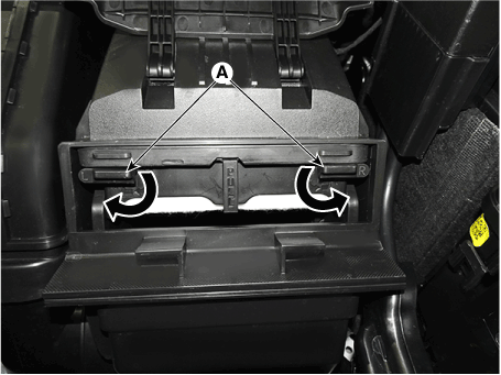
| 3. |
Replace the air cleaner element (A) with a new one.
|
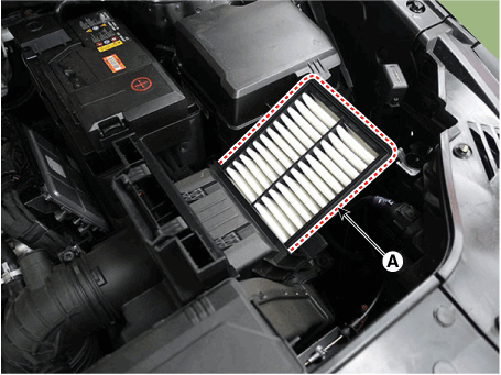

| 4. |
Lock the air cleaner element camshaft and then close the air cleaner
element cover.
|
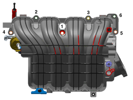
Intake Manifold. Repair procedures
| Removal and Installation |
| 1. |
Disconnect the battery negative teminal.
|
| 2. |
Remove the engine cover.
(Refer to Engine and Transaxle Assembly - "Engine Cover")
|
| 3. |
Remove the air duct and air cleaner assembly.
(Refer to Intake and Exhaust System - "Air Cleaner")
|
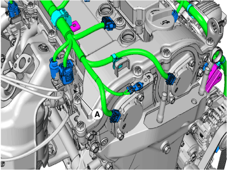
| 4. |
Disconnect the wiring connectors and harness clamps and remove the wiring
protector around the intake manifold.
|
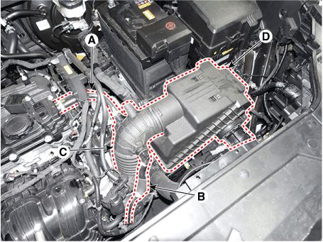
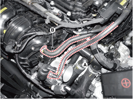
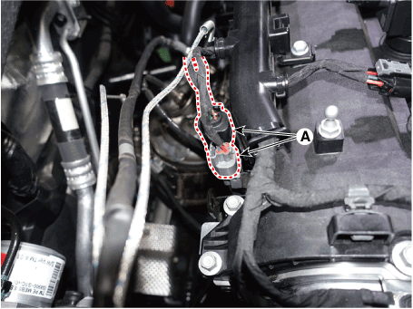
| 5. |
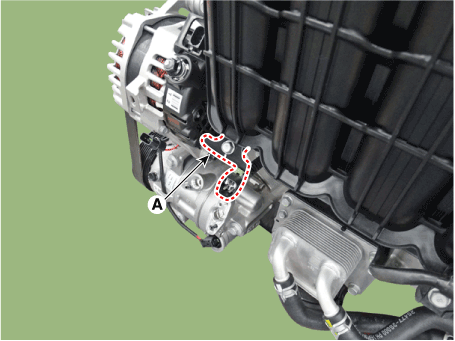
Disconnect the purge control solenoid valve (PCSV) hose (A) and vacuum
hose (B).
|
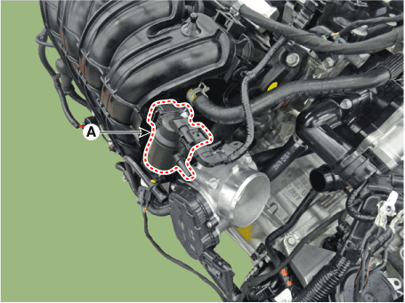
| 6. |
Remove the purge control solenoid valve (PCSV) bracket (A) from intake
manifold.
|
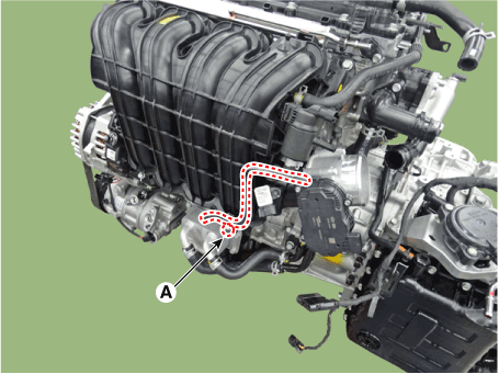
| 7. |
Remove the wiring bracket (A).
|
| 8. |
Remove the breather hose mounting bolt (A)
|
| 9. |
Remove the intake manifold stay.
|
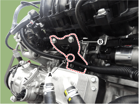
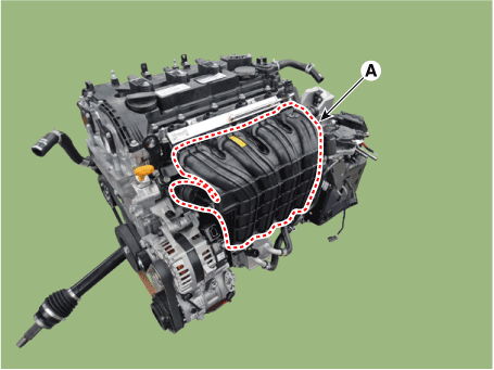
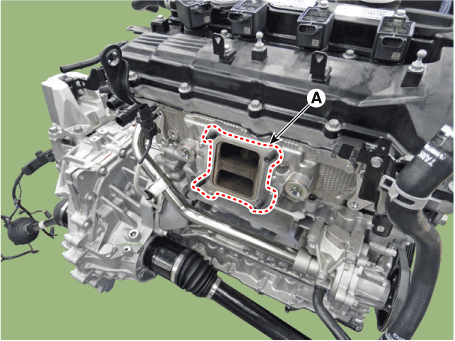
| 10. |
Remove the Intake Manifold (A).
|
| 11. |
Remove the electronic throttle control (ETC) module.
(Refer to Engine Control/ Fuel System - "ETC (Electronic Throttle Control")
|
| 12. |
Install in the reverse order of removal.
|
Exhaust Manifold. Repair procedures
| Removal and Installation |
|

| 1. |
Disconnect the battery negative terminal.
|
| 2. |
Remove the engine cover.
(Refer to Engine and Transaxle Assembly System - "Engine cover")
|
| 3. |
Remove the engine room under cover.
(Refer to Engine and Transaxle Assembly System - "Engine Room Under
Cover")
|
| 4. |
Disconnect the front oxygen sensor connectors (A).
|
| 5. |
Remove the front muffler.
(Refer to Intake and Exhaust Manifold - "Front Muffler")
|
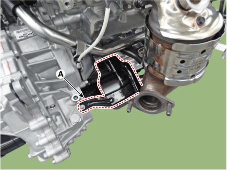
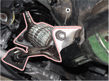
| 6. |
Remove the exhaust manifold stay (A).
|
| 7. |
Remove the drive shaft heat protector (A).
|
| 8. |
Remove the engine mounting support bracket.
(Refer to Engine and Transaxle Assembly - "Engine Mounting")
|
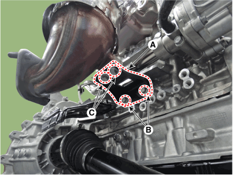
| 9. |
Remove the exhaust manifold (A).
|
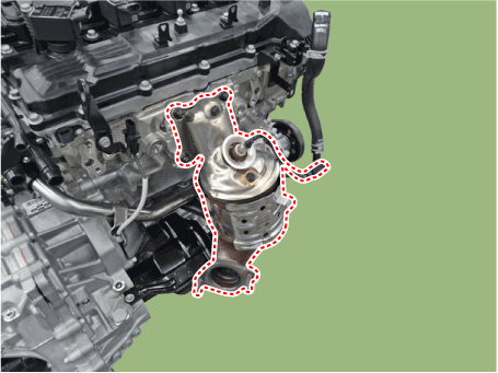
| 10. |
Remove the exhaust manifold gasket (A).
|
| 11. |
Install in the reverse order of removal.
|
Muffler. Repair procedures
| Removal and Installation |
|
[Front Muffler]
| 1. |
Disconnect the battery negative terminal.
|
| 2. |
Disconnect the oxygen sensor connector (A) and then disconnect from
bracket.
|
| 3. |
Remove the engine room rear under cover (A).
|
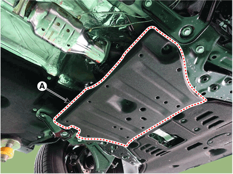
| 4. |
Remove the front muffler (A).
|
| 5. |
Install in the reverse order of removal.
|
Replacing procedures of catalytic converter using clamp
| 1. |
Check that the clamping part of the main muffler assembly is damaged
or deformed.
|
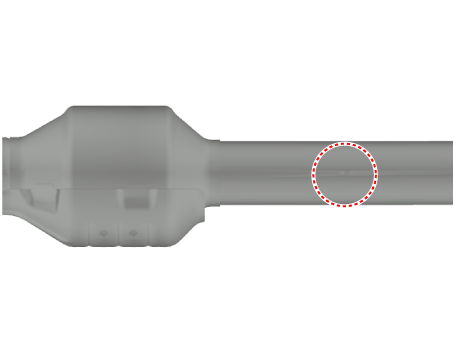
| 2. |
Cut the main muffler as indicated below.
|
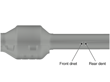
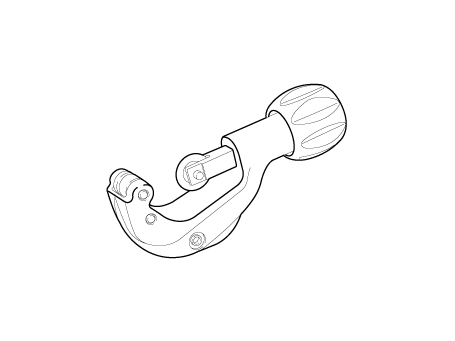
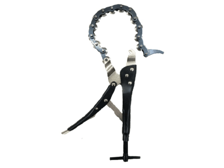
| 3. |
Replace the catalytic converter.
|
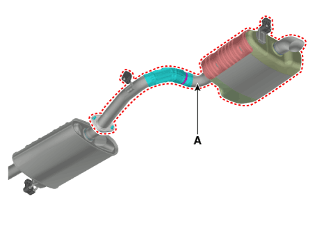
Catalytic Converter and Center Muffler
| 1. |
Remove the catalytic converter and center muffler (A).
|
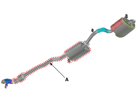
| 2. |
Install in the reverse order of removal.
|
Rear Muffler
| 1. |
Remove the rear muffler (A).
|
| 2. |
Install in the reverse order of removal.
|
 Lubrication System
Engine Oil. Repair procedures Oil and filter replacement • Be careful not to damage the parts located under the vehicle (floor under cover, fuel filter, fuel tank and canister) when raising ...

See also:
Seat Belt Pretensioner (BPT). Components and Components Location
Components ...
Limitation of Active ECO operation
If the following conditions occur while Active ECO is operating, the system operation is limited even though there is no change in the ECO indicator. When the coolant temperature is low: The system will ...
Highway driving
Tires: Adjust the tire inflation pressures to specification. Low tire inflation pressures will result in overheating and possible failure of the tires. Avoid using worn or damaged tires which may result ...
