 Hyundai Santa Fe (TM): Crankcase Emission Control System
Schematic diagrams
| Schematic Diagram |
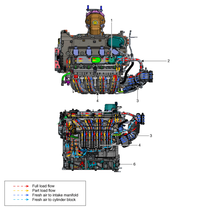
| 1. PCV Valve 2. Breather hose 3. Air intake hose |
4. Intake maifold 5. Air breather hose 6. Cylinder block |
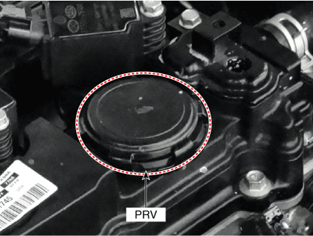
Positive Crankcase Ventilation (PCV) Valve. Description and operation
| Description |
Pressure Regulating Valve (PRV) is installed to prevent the over pressure of
combustion gas through the piston ring and onto the crankcase.
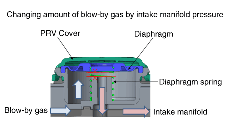
| Operation Principle |
|
Engine Condition |
Stop |
Idle or Deceleration |
Normal operating condition |
Accelerating in the high load area |
|
Intake manifold pressure |
0 |
High |
Appropriate |
Low |
|
PRV (Diaphragm) |
Full open |
A little open |
Appropriate open |
Considerable open |
|
Amount of blow-by gas |
0 |
A little |
Middle |
A lot |
|
Diaphragm component part |
|
|||
Positive Crankcase Ventilation (PCV) Valve. Repair procedures
| Removal |
| 1. |
Remove the cylinder head cover.
(Refer to Engine Mechanical System - "Cylinder Head Cover")
|
| Installation |
| 1. |
Install in the reverse order of removal.
|
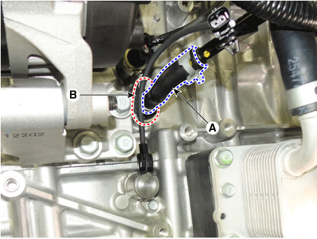
Crankcase Check Valve. Repair procedures
| Removal and Installation |
|

| 1. |
Disconnect the battery (-) terminal.
|
| 2. |
Remove the engine room under cover.
(Refer to Engine And Transaxle Assembly - "Engine Room Under Cover")
|
| 3. |
Remove the drive belt.
(Refer to Drive Belt System - "Drive Belt")
|
| 4. |
Remove the compressor mounting bolts.
(Refer to Heating, Ventilation and Air Conditioning - "Compressor")
|
| 5. |
Disconnect the crankcase check valve hose (A) and then remove the crankcase
check valve (B).
|

 Schematic diagrams
Schematic Diagram ...
 Evaporative Emission Control System
Description and operation Description Evaporative Emission Control System prevents fuel vapor stored in fuel tank from vaporizing into the atmosphere. When the fuel evaporates in the fuel tank, the vapor ...
See also:
Instrument Cluster. Components
and Components Location
Components Connector Pin Information No. Description No. Description 1 - 21 - 2 Illumination output 22 - 3 Rheostat down switch 23 4P output 4 Rheostat up switch 24 Immobilizer 5 AT N output 25 AT S output ...
Hood Assembly. Components and Components Location
Component Location 1. Hood assembly ...
Rear Wheel Speed Sensor. Repair procedures
Removal 4WD only 1. Remove the rear wheel and tire. Tightening torque: 88.3 ~ 107.9 N.m (9.0 ~ 11.0 kgf.m, 65.1 ~ 79.6 lb-ft) 2. Remove the rear wheel speed sensor mounting bolt (A). Tightening torque: ...
