 Hyundai Santa Fe (DM): Sub Frame. Repair procedures
Removal
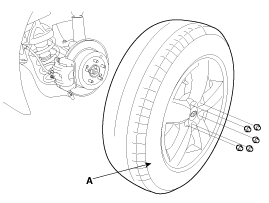
| 1. |
Remove the front wheel and tire (A) from front hub .
|
| 2. |
Disconnect the stabilizer link(B) with the front strut assembly(A)
after loosening the nut.
|
| 3. |
Remove the sprit pin and castle nut and then disconnect the tie-rod
end (A) from the front knuckle.
|
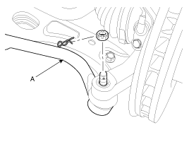
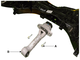
| 4. |
Loosen the bolt & nut and then remove the lower arm (A).
|
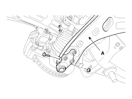
| 5. |
Loosen the bolt (A) and then disconnect the universal joint assembly
from the pinion of the steering gear box.
|
| 6. |
Remove the under cover.
|
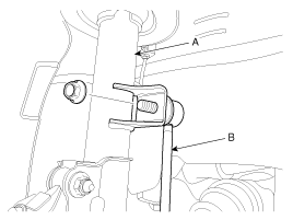
| 7. |
Loosen the bolt (A,B) and then remove the upper roll rod bracket.
|
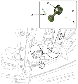
| 8. |
Remove the roll rod stopper bolt (A).
|
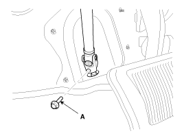
| 9. |
Disconnect the muffler rubber hanger (A).
|
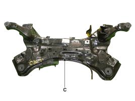
| 10. |
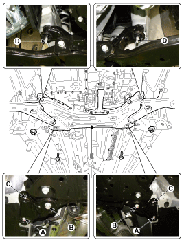
Loosen the bolts & nuts and then remove the sub frame.
|
| 11. |
Loosen the bolt (A-4ea) and then remove the stabilizer bar (B)
from the sub frame.
|
| 12. |
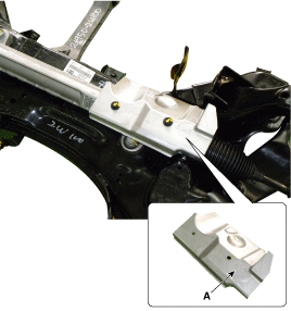
Loosen the bolt and then remove the protector (A).
|
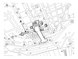
| 13. |
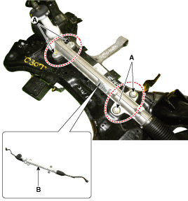
Remove the steering gearbox (B) from the cross member by loosening
the mounting bolt (A-4ea).
|
| 14. |
Loosen the nut (A-2ea) and then remove the sub frame damper (B).
|
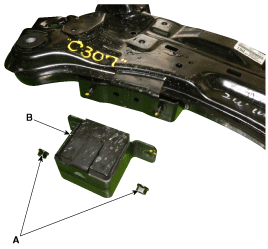
| 15. |
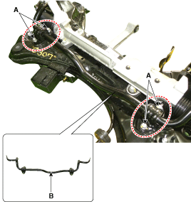
Remove the front lower arm.
|
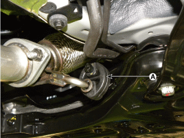
| 16. |
Loosen the bolt (A-2ea) and then remove the roll rod stopper (B)
from the sub frame (C).
|
| 17. |
Installation is the reverse of removal.
|
| 18. |
Check the front alignment.
|
 Front Stabilizer Bar. Repair procedures
Removal 1. Remove the front wheel and tire (A) from front hub . Tightening torque: 88.2 ~ 107.8 N.m (9.0 ~ 11.0 kgf.m, 65.0 ~ 79.5 lb-ft) Be careful not to damage to the hub bolts when removing the front ...

See also:
Rear Center Seat Belt Retractor. Repair procedures
Replacement • When installing the belt, make sure not to damage the retractor. 1. Remove the second row seat back cover [LH]. 2. Loosen the rear center seat belt lower anchor mounting bolt (A). Tightening ...
Important Safety Notice
Important Safety Notice Proper service methods and repair procedures are essential for safe, reliable operation of all motor vehicles as well as personal safety of the operator. The service procedures ...
Front Alignment. Repair procedures
Front wheel alignment When using a commercially available computerized wheel alignment equipment to inspect the front wheel alignment, always position the vehicle on a level surface with the front wheels ...
