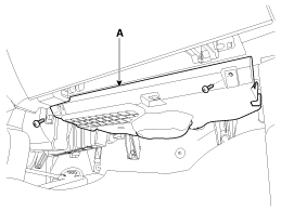
Replacement • Put on gloves to protect your hands. • When prying with a flat-tip screwdriver, wrap it with protective tape, and apply protective tape around the related parts, to prevent damage. • ...
See also:
Rear Door Latch. Repair procedures
Replacement 1. Remove the rear door module. 2. Remove the rear door outside handle base (A) by pushing in the lock pins located in the back. 3. Remove the rear door outside handle base cable (A). 4. Open ...
To fold down the rear center seatback
1. Lower the rear headrests to the lowest position. 2. Push the center seatback folding lever up, then fold the seat toward the front of the vehicle. When you return the seatback to its upright position, ...
Cruise Control Switch. Components and Components Location
Components 1. Remote control switch (LH: Audio) 2. Remote control switch (RH: Cruise + Flex) 3. Bluetooth handfree switch 4. Trip switch ...
 Hyundai Santa Fe: Crash Pad Under Cover. Repair procedures
 Crash Pad Side Cover. Repair procedures
 Crach Pad Center Panel. Components and Components Location
