 Hyundai Santa Fe: Rear Alignment. Repair procedures
Rear wheel alignment
When using a commercially available computerized wheel alignment
equipment to inspect the rear wheel alignment, always position the vehicle
on a level surface.
Prior to inspection, make sure that the rear suspension system
is in normal operating condition and that the tires are inflated to
the specified pressure.
|
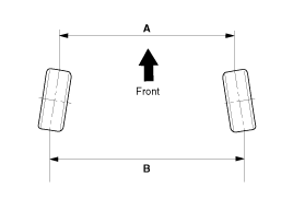
Toe

B - A. 0: Toe in (+)
B - A < 0: Toe out (-)
|
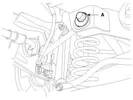
Toe adjustment
| 1. |
Loosen the nut holding the assist arm cam bolt (A).
|
| 2. |
Adjust rear toe by turning the rear assist arm cam bolt (A) clockwise
or counter clockwise. Toe adjustment should be made by turning the right
and left cam bolt by the same amount.
|
| 3. |
When completing the toe adjustment, tighten the nut to specified
torque.
|
Camber
Camber is pre-set at the factory, so it does not need to be adjusted.
If the camber is not within the standard value, replace or repair the damaged
parts and then inspect again.
Camber : -1° ± 0.5°
|
 Components and Components Location
Components 2WD 1. Rear upper arm 2. Rear stabilizer bar 3. Rear lower arm 4. Rear assist arm 5. Rear shock absorber 6. Rear cross member 7. Trailing arm 4WD 1. Rear assist arm 2. Rear cross member 3. Rear ...
 Rear Shock Absorber. Repair procedures
Removal 2WD 1. Remove the rear wheel and tire (A) from rear hub . Tightening torque: 88.2 ~ 107.8 N.m (9.0 ~ 11.0 kgf.m, 65.0 ~ 79.5 lb-ft) Be careful not to damage to the hub bolts when removing the rear ...
See also:
Fuse switch
Always, put the mode switch at the ON position. If you move the switch to the OFF position, some items such as audio and digital clock must be reset and transmitter (or smart key) may not work properly. ...
Front Seat Assembly. Repair procedures
Replacement 1. Remove the front seat track mounting cover. 2. After loosening the mounting bolts, remove the front seat assembly (A). Tightening torque : 34.3 ~ 53.9 N.m (3.5 ~ 5.5 kgf.m, 25.3 ~ 39.8 lb-ft) ...
Indicator light
When ignition switch is turned to ON, the indicator light illuminates, then goes off if the ESC system is operating normally. The ESC indicator light blinks whenever ESC is operating or illuminates when ...

