
 Hyundai Santa Fe: Rear Hub - Carrier. Repair procedures
Removal
| 1. |
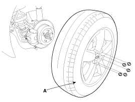
Remove the front wheel and tire (A) from front hub.
|

| 2. |
Remove the rear brake caliper.
|
| 3. |
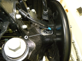
Remove the wheel speed sensor (A), from the knuckle.
|
| 4. |
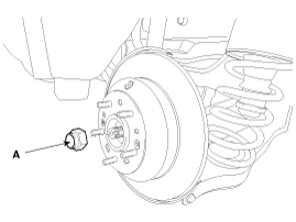
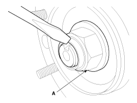
Remove the coking nut (A).
|
| 5. |
Remove the parking brake cable.
|
| 6. |
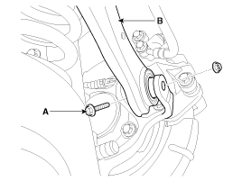
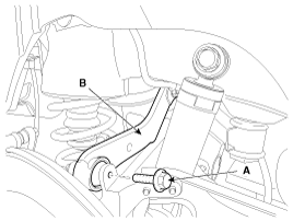
Remove the rear upper arm (A) after loosen the bolt (B).
[2WD]
[4WD]
|
| 7. |
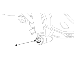
Remove the rear strut assembly (C) after loosen the bolt (B) and
nut (A).
|
| 8. |
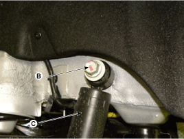
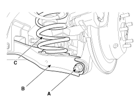
Remove the rear lower arm (B), spring (C) as loosening bolt (A)
after supporting rear lower arm (B) with jack.
|
| 9. |
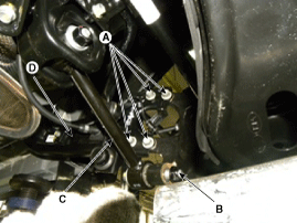
Remove the rear assist arm (C), trailing arm (D) as loosening
bolt (A), nut (B).
|
| 10. |
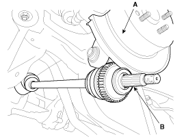
Separate the end (B) of rear driveshaft on rear axle assembly
(A).
|
| 11. |
Install in the reverse order of removal.
|
| 12. |
Check the rear alignment.
|
Disassembly
| 1. |
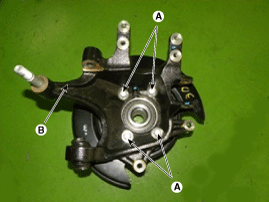
Remove the hub assembly mounting bolts (A-4ea) from the rear axle
carrier (B).
|
| 2. |
Remove the hub assembly (C) and the parking brake assembly (B)
from the rear axle carrier (A).
|
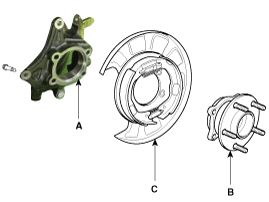
| 3. |
Assembly is the reverse order of disassembly.
|
Inspection
| 1. |
Check the hub for cracks and the splines for wear.
|
| 2. |
Check the rear axle carrier for cracks.
|
 Rear Hub - Carrier. Components and Components Location
Components 1. Rear carrier assembly 2. Parking brake assembly 3. Rear hub assembly 4. Rear brake disc ...

See also:
Height Adjust. Components and Components Location
Component Location 1. Height adjust ...
Alternator. Specifications
Specification Alternator Item Specification Rated voltage 13.5V, 130A Speed in use 1,000 ~ 18,000 rpm Voltage regulator IC Regulator built-in type Regulator Setting Voltage External mode Refer to below ...
Components and Components Location
Components 1. Roof side moulding [LH] 2. Roof side moulding [RH] 3. Movable Glass 4. Slide 5. Cover base 6. Wind deflector 7. Center cover 8. Panorama sunroof frame assembly 9. Mechanism rail assembly ...
