 Hyundai Santa Fe: Schematic Diagrams
Schematic Diagrams
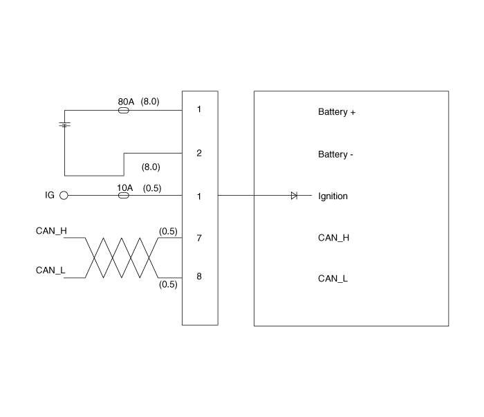
MDPS Circuit Diagram

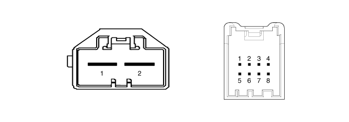
Harness Connector

|
Connector |
Pin no |
Pin name |
|
Battery |
1 |
Battery + |
|
2 |
Battery - |
|
|
Vehicle signal |
1 |
Igntion |
|
2 |
- |
|
|
3 |
- |
|
|
4 |
- |
|
|
5 |
- |
|
|
6 |
- |
|
|
7 |
CAN_High |
|
|
8 |
CAN_Low |
 Components and Components Location
Components 1. Steering column shaft 2. ECU 3. Motor 4. Steering gear box ...
 Repair procedures
General Inspection After or before servicing the EPS system, perform the troubleshooting and test procedure as follows. Compare the system condition with normal condition in the table below and if abnormal ...
See also:
Welcome system
Headlamp welcome When the headlight(light switch in the headlight or AUTO position) is on and all doors (and tailgate) are locked and closed, the headlight, position light and tail light will come on for ...
Blade inspection
✽ NOTICE Commercial hot waxes applied by automatic car washes have been known to make the windshield difficult to clean. Contamination of either the windshield or the wiper blades with foreign ...
Closing the tailgate
To close the tailgate, lower and push down the tailgate firmly. Make sure that the tailgate is securely latched. WARNING - Exhaust fumes If you drive with the tailgate open, you will draw dangerous exhaust ...
