 Hyundai Santa Fe (TM): Timing System
Components and components location
| Components |
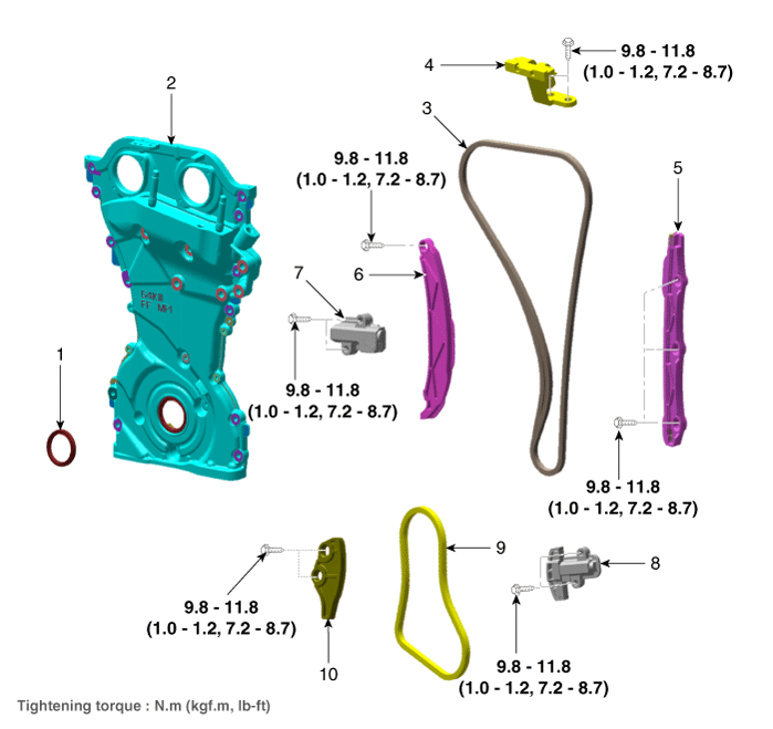
| 1. Front oil
seal 2. Timing chain cover 3. Timing chain 4. Cam to cam bracket 5. Timing chain guide |
6. Timing chain
tensioner arm 7. Timing chain tensioner 8. Oil pump chain tensioner 9. Oil pump chain 10. Oil pump chain guide |
Front Oil Seal. Repair procedures
| Removal and Installation |
|
| 1. |
Remove the crankshaft damper pulley.
(Refer to Timing System - "Crankshaft Damper Pulley")
|
| 2. |
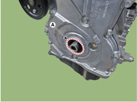
Remove the front oil seal (A).
|
| 3. |
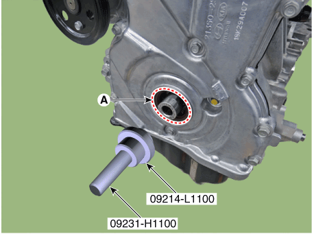
Install the crankshaft front oil seal (A) using SST (09214 - L1100,
09231-H1100).
|
Timing Chain Cover. Repair procedures
| Removal |
|
|
|
|
| 1. |
Disconnect the battery negative terminal.
|
| 2. |
Remove the engine cover.
(Refer to Engine and Transaxle Assembly - "Engine Cover")
|
| 3. |
Remove the RH front wheel.
(Refer to Suspension System - "Wheel")
|
| 4. |
Remove the engine room under cover.
(Refer to Engine and Transaxle Assembly - "Engine Room Under Cover")
|
| 5. |
Remove the cylinder head cover.
(Refer to Cylinder Head Assembly - "Cylinder Head Cover")
|
| 6. |
Remove the compressor.
(Refer to Heating, Ventilation Air conditioning - "Compressor")
|
| 7. |
Remove the A/C compressor bracket.
(Refer to Lubrication System - "Oil Pan")
|
| 8. |
Remove the oil pan.
(Refer to Lubrication System - "Oil Pan")
|
| 9. |
Remove the engine mounting bracket.
(Refer to Engine And Transaxle Assembly - "Engine Mounting")
|
| 10. |
Install the jack to the edge of ladder frame.
|
| 11. |
Remove the crankshaft damper pulley.
(Refer to Drive Belt System - "Crankshaft Damper Pulley")
|
| 12. |
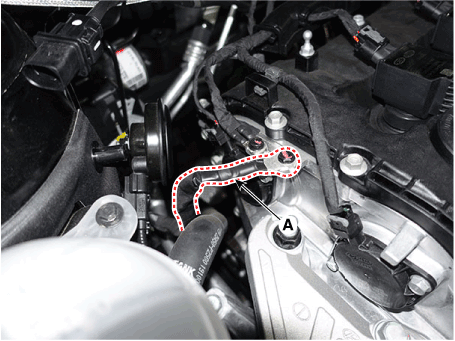
Disconnect the engine ground cable (A).
|
| 13. |
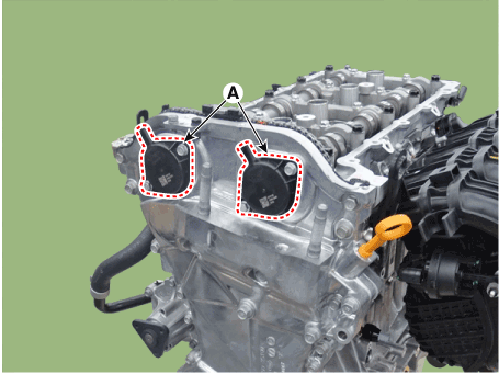
Remove the intake and exhaust variable force solenoid (VFS) valves (A).
|
| 14. |
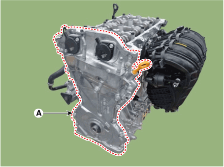
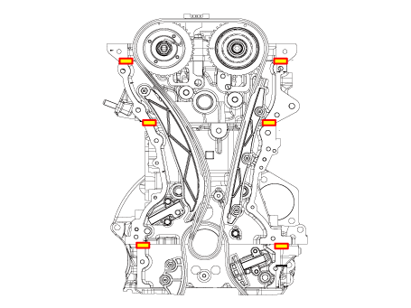
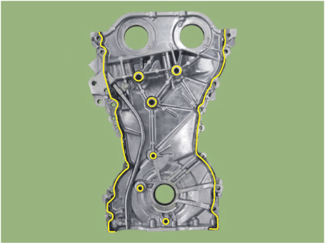
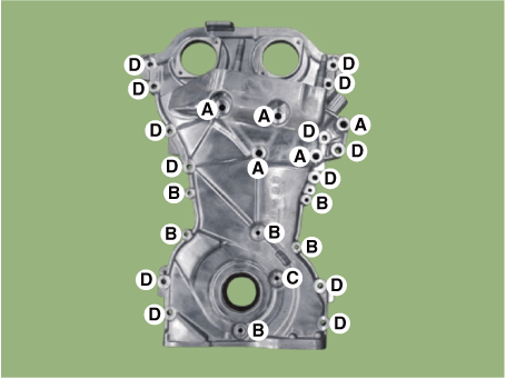
Remove the timing chain cover (A).
|
| Installation |
| 1. |
Install the timing chain cover.
|
| 2. |
Replace the front oil seal if necessary.
(Refer to Timing System - ŌĆ£Front Oil SealŌĆØ)
|
| 3. |
Install the other parts in the reverse order of removal.
|
Timing Chain. Repair procedures
| Removal |
|
| 1. |
Remove the cylinder head cover.
(Refer to Cylinder Head Assembly - "Cylinder Head Cover")
|
| 2. |
Set No.1 cylinder to top dead center (TDC) on compression stroke.
|
| 3. |
Remove the timing chain cover.
(Refer to Timing System - "Timing Chain Cover")
|
| 4. |
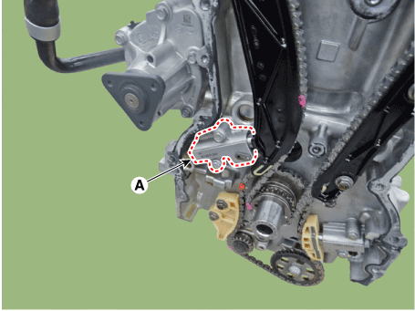
Remove the timing chain tensioner (A).
|
| 5. |
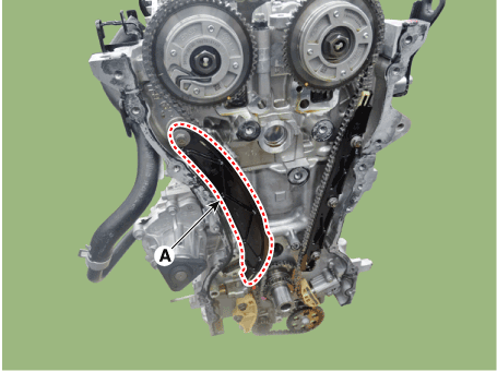
Remove the timing chain tensioner arm (A).
|
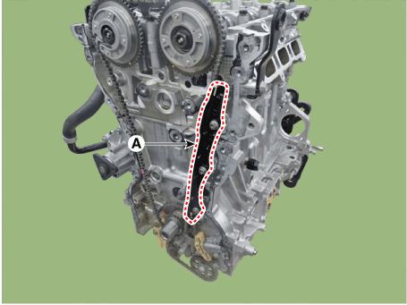
| 6. |
Remove the timing chain guide (A).
|
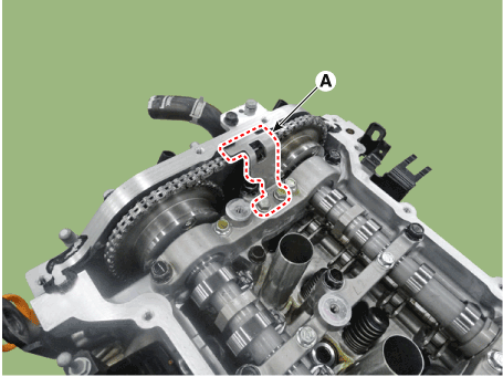
| 7. |
Remove the cam to cam guide (A).
|
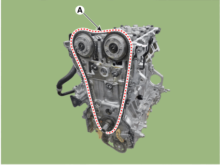
| 8. |
Remove the timing chain (A).
|
| Inspection |
Sprockets, Hydraulic Tensioner, Chain Guide, Tensioner Arm, Timing Chain
| 1. |
Check the CVVT sprocket, crankshaft sprocket teeth for abnormal wear,
cracks or damage. Replace if necessary.
|
| 2. |
Check a contact surface of the chain tensioner arm and guide for abnormal
wear, cracks or damage.
Replace if necessary.
|
| 3. |
Check the hydraulic tensioner for its piston stroke and ratchet operation.
Replace if necessary.
|
| 4. |
Check the timing chain for its elongation, abnormal wear or damage.
Replace if necessary.
|
| Installation |
| 1. |
Install the timing chain (A).
|
| 2. |
Install the timing chain guide (A).
|
| 3. |
Install the timing chain tensioner arm (A).
|
| 4. |
Install the timing chain tensioner (A) and then remove the timing chain
tensioner fixing pin.
|
| 5. |
Install the cam to cam guide (A).
|
| 6. |
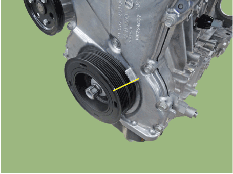
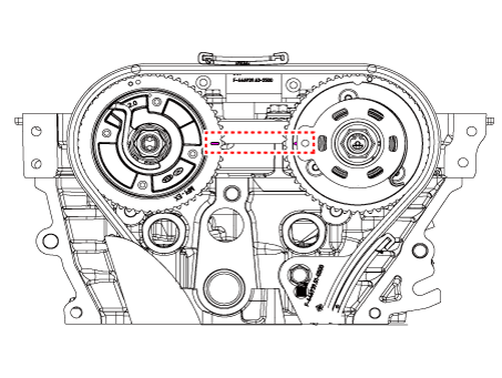
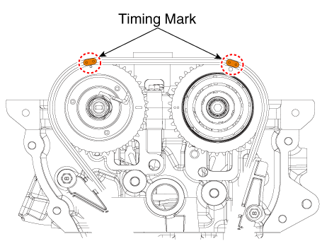
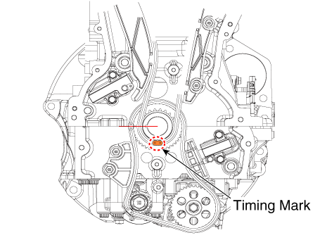
Check if the TDC mark at the front of intake and exhaust CVVT on right
side 0┬░ by turning crankshaft twice to clockwise.
[CVVT timing mark]
[Crankshaft sprocket timing mark]
|
| 7. |
Install the timing chain cover.
(Refer to Timing System - "Timing Chain Cover")
|
| 8. |
Install the other parts in the reverse order of removal.
|
 Drive Belt System
Drive Belt. Repair procedures Removal ŌĆó Be careful not to damage the parts located under the vehicle (floor under cover, fuel filter, fuel tank and canister) when raising the vehicle using ...
 Cylinder Head Assembly
Components and components location Components 1. Camshaft front bearing cap 2. Camshaft bearing cap 3. OCV & Center bolt 4. Exhaust CVVT assembly 5. Exhaust camshaft 6. Intake camshaft 7. Intake CVVT ...
See also:
All wheel drive (AWD)
Engine power can be delivered to all front and rear wheels for maximum traction. AWD is useful when extra traction is required, such as, when driving on slippery, muddy, wet, or snow-covered roads. These ...
Schematic Diagrams
System Block Diagram Component Parts And Function Outline Component part Function Vehicle-speed sensor Converts vehicle speed to pulse. ECM Receives signals from sensor and control switches. Cruise control ...
AUX(Auxiliary) Jack. Schematic Diagrams
Circuit Diagram ...


