
 Hyundai Santa Fe: Automatic Transaxle. Repair procedures
Removal
| 1. |
Remove the engine cover.
|
| 2. |
Remove the air cleaner assembly and air duct.
|
| 3. |
Remove the battery and battery tray.
|
| 4. |
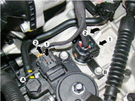
Disconnect the inhibitor switch connect (A) and solenoid valve
connector (B).
|
| 5. |
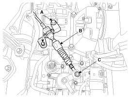
Remove the shift cable (B) after removing the nut (C) and the
bolt (A).
|
| 6. |
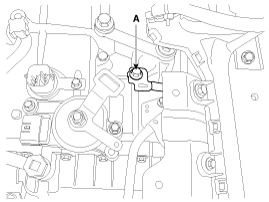
Remove the ground line after removing the bolt (A).
|
| 7. |
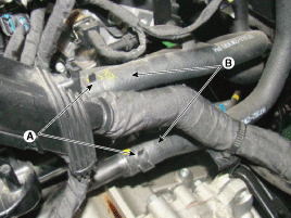
Disconnect the coolant hose (B) after removing the automatic transaxle
coolant hose clamp (A).
|
| 8. |
Remove the wiring mounting clip (C).
|

| 9. |
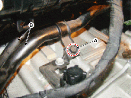
Remove the coolant pipe mounting bolts (A).
|
| 10. |
Remove the coolant pipe(B).
|
| 11. |
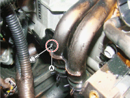
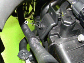
Remove the wiring bracket installation bolt (A).
|
| 12. |
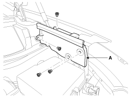
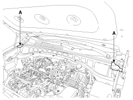
After loosening the mounting clips, then remove the fender side
cover (A).
|
| 13. |
Disconnect the pad(A).
|
| 14. |
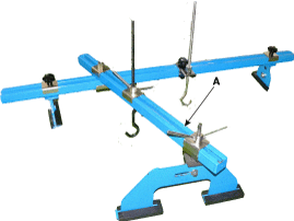
Assembled the engine support fixture (A).
|
| 15. |
Remove the hood.
|
| 16. |
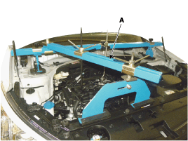
Using the engine support fixture (A) , hold the engine and transaxle
assembly safely.
|
| 17. |
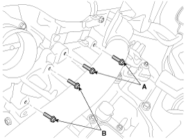
Remove the automatic transaxle upper mounting bolt (A-2ea) and
the starter motor mounting bolt (B-2ea).
|
| 18. |
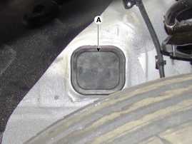
Remove the mounting bracket cover (A).
|
| 19. |
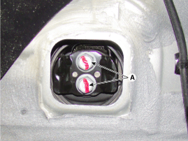
Remove the automatic transaxle mounting bracket bolt (A).
|
| 20. |
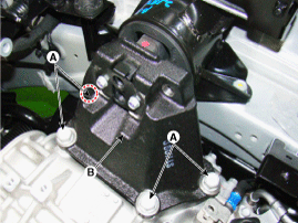
Remove the automatic transaxle mounting support bracket bolts
(A).
|
| 21. |
Remove the automatic transaxle mounting support bracket (B).
|
| 22. |
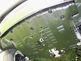
Remove the under cover (A).
|
| 23. |
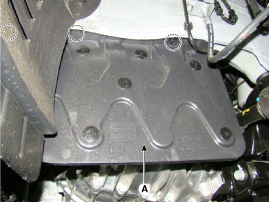
Remove the side cover (A).
|
| 24. |
Remove the following items;
2WD
4WD
|
| 25. |
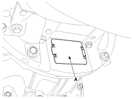
Remove the dust cover(A).
|
| 26. |
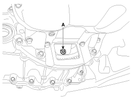
Remove the torque converter mounting bolt (A) with rotating the
crankshaft.
|
| 27. |
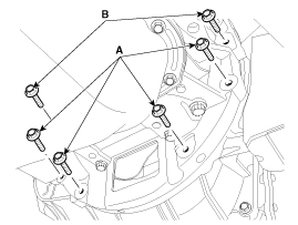
Remove the automatic transaxle with a jack after removing the
mounting bolt (A-4ea, B-2ea).
|
Installation
| 1. |
Installation is the reverse of removal.
|


 Automatic Transaxle. Components and Components Location
Components Location 1. Automatic transaxle 2. Shift cable bracket 3. Inhibitor switch connector 4. Manual control lever 5. Automatic transaxle mounting support bracket 6. Solenoid valve connector 7. ATF ...
 Hydraulic System
...
See also:
Side impact air bag
❈ The actual air bags in the vehicle may differ from the illustration. Your vehicle is equipped with a side impact air bag in each front seat. The purpose of the air bag is to provide the vehicle's ...
Description and Operation
Description Automatic transaxle system relies on various measurement data to determine the current control status and extrapolate the necessary compensation values. These values are used to control the ...
Front Wheel Components and Components Location
Components Location 1.Under cover 2. Transaxle Assembly 3. Transfer assembly 4. Propeller shaft 5. Coupling assembly ...
