 Hyundai Santa Fe: ETC (Electronic Throttle Control) System. Repair procedures
Inspection
Throttle Position Sensor (TPS)
| 1. |
Connect the GDS on the Data Link Connector (DLC).
|
| 2. |
Start the engine and measure the output voltage of TPS 1 and 2
at C.T. and W.O.T.
|
| 3. |
Turn the ignition switch OFF and disconnect the scantool from
the DLC.
|
| 4. |
Disconnect the ETC module connector and measure the resistance
between the ETC module terminals 1 and 2.
|
ETC Motor
| 1. |
Turn the ignition switch OFF.
|
| 2. |
Disconnect the ETC module connector.
|
| 3. |
Measure resistance between the ETC module terminals 3 and 6.
|
| 4. |
Check that the resistance is within the specification.
|
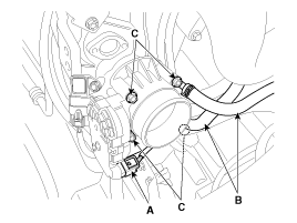
Removal
| 1. |
Turn the ignition switch OFF and disconnect the battery negative
(-) cable.
|
| 2. |
Remove the resonator and the air intake hose.
(Refer to Engine Mechanical System - "Air Cleaner")
|
| 3. |
Disconnect the ETC module connector (A).
|
| 4. |
Disconnect the coolant hoses (B).
|
| 5. |
Remove the installation bolts (C), and then remove the ETC module
from the engine.
|
Installation
|
| 1. |
Install in the reverse order of removal.
|
 ETC (Electronic Throttle Control) System. Schematic Diagrams
Circuit Diagram ...
 Manifold Absolute Pressure Sensor (MAPS). Description and Operation
Description Manifold Absolute Pressure Sensor (MAPS) is a speed-density type sensor and is installed on the surge tank. It senses absolute pressure of the surge tank and transfers the analog signal proportional ...
See also:
Under Body. Body Repair
Under Body (2WD) Projected Dimensions * These dimensions indicated in this figure are actual-measurement dimensions. [ Unit : mm (inch) ] Actual-Measurement Dimensions * These dimensions indicated in this ...
Engine Coolant Temperature Sensor (ECTS). Specifications
Specification Temperature Resistance (kΩ) °C °F -40 -40 48.14 -20 -4 14.13 ~ 16.83 0 32 5.79 20 68 2.31 ~ 2.59 40 104 1.15 60 140 0.59 80 176 0.32 ...
Scheduled maintenance service
Follow Normal Maintenance Schedule if the vehicle is usually operated where none of the following conditions apply. If any of the following conditions apply, follow Maintenance Under Severe Usage Conditions. ...

