
 Hyundai Santa Fe: Instrument Cluster. Components
and Components Location
Hyundai Santa Fe: Instrument Cluster. Components
and Components Location
Components
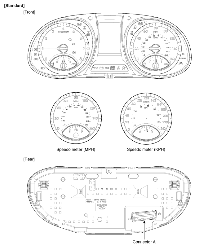
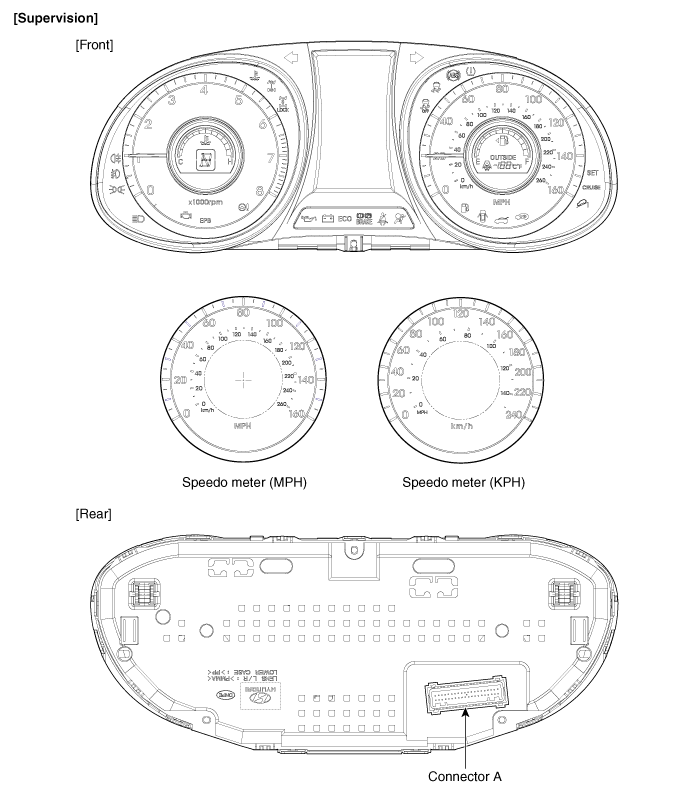
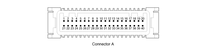
|
No. |
Description |
No. |
Description |
|
1 |
- |
21 |
- |
|
2 |
Illumination output |
22 |
- |
|
3 |
Rheostat down switch |
23 |
4P output |
|
4 |
Rheostat up switch |
24 |
Immobilizer |
|
5 |
AT N output |
25 |
AT S output |
|
6 |
Oil pressure |
26 |
AT R output |
|
7 |
Low washer |
27 |
AT P output |
|
8 |
Charge |
28 |
- |
|
9 |
AT D output |
29 |
- |
|
10 |
Illumination + |
30 |
MM_CAN High |
|
11 |
- |
31 |
MM_CAN Low |
|
12 |
Active ECO |
32 |
C_CAN High |
|
13 |
Heated wheel indicator |
33 |
C_CAN Low |
|
14 |
Fuel |
34 |
Trip switch1 |
|
15 |
Detent output |
35 |
Trip switch2 |
|
16 |
Fuel ground |
36 |
Trip switch ground |
|
17 |
- |
37 |
Signal ground |
|
18 |
Speaker - |
38 |
- |
|
19 |
Speaker + |
39 |
IGN + |
|
20 |
Aig bag + |
40 |
Battery + |
 Components and Components Location
Component Location 1. Cluster assembly 2. Seat belt switch 3. Vehicle speed sensor 4. Engine coolant temperature sender 5. Oil pressure switch 6. Brake fluid level warning switch 7. Parking brake switch ...
 Instrument Cluster. Schematic
Diagrams
Instrument Cluster. Schematic
Diagrams
Circuit Diagram ...
See also:
Repair procedures
General Inspection After or before servicing the EPS system, perform the troubleshooting and test procedure as follows. Compare the system condition with normal condition in the table below and if abnormal ...
Child-protector rear door lock
The child safety lock is provided to help prevent children from accidentally opening the rear doors from inside the vehicle. The rear door safety locks should be used whenever children are in the vehicle. ...
Overdrive Clutch Control Solenoid Valve(OD/C_VFS). Specifications
Specifications Direct control VFS[OD/C] ▷ Control type : Normal high type Control Pressure kpa (kgf/cm², psi) 500.14~9.81 (5.1~0.1,72.54~1.42) Current value(mA) 50~850 Internal resistance(Ω) ...
