 Hyundai Santa Fe: Manifold Absolute Pressure Sensor (MAPS). Repair procedures
Inspection
| 1. |
Connect the GDS on the Data Link Connector (DLC).
|
| 2. |
Measure the output voltage of the MAPS at idle and IG ON.
|
Removal
| 1. |
Turn the ignition switch OFF and disconnect the battery negative
(-) cable.
|
| 2. |
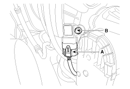
Disconnect the manifold absolute pressure sensor connector (A).
|
| 3. |
Remove the installation bolt (B), and then remove the sensor from
the surge tank.
|
Installation
|
|
| 1. |
Install in the reverse order of removal.
|
 Manifold Absolute Pressure Sensor (MAPS). Schematic Diagrams
Circuit Diagram ...
 Intake Air Temperature Sensor (IATS). Description and Operation
Description Intake Air Temperature Sensor (IATS) is included inside Manifold Absolute Pressure Sensor and detects the intake air temperature. To calculate precise air quantity, correction of the air temperature ...
See also:
Rear parking assist system precautions
The rear parking assist system may not sound sequentially depending on the speed and shapes of the objects detected. The rear parking assist system may malfunction if the vehicle bumper height or sensor ...
Steering Angle Sensor. Description and Operation
Description The Steering Angle Sensor (SAS) is installed in MDPS (Motor Driven Power Steering) and it sends messages to HECU through CAN communication line. The SAS is used to determine turning direction ...
Storage compartment
CAUTION To avoid possible theft, do not leave valuables in the storage compartments. Always keep the storage compartment covers closed while driving. Do not attempt to place so many items in the storage ...

