 Hyundai Santa Fe: Schematic Diagrams
Circuit Diagram

 Components and Components Location
Component Location 1. Automatic transaxle 2. Inhibitor switch 3. Transaxle Control Module (TCM) 4. Valve body cover 5. Solenoid valve connect 6. Oil temperature sensor 7. Valve body assembly 8. Line Pressure ...
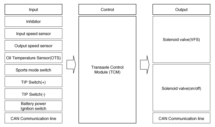
 Transaxle Control Module (TCM). Description and Operation
Description Transaxle Control Module (TCM) is the automatic transaxle's brain. The module receives and processes signals from various sensors and implements a wide range of transaxle controls to ensure ...
See also:
Rear Washer Switch. Repair procedures
Inspection 1. Check for continuity between the terminals while operating the wiper and washer switch. If it is not normal condition, replace wiper and wiper switch. Rear Wiper Switch Rear Washer Switch ...
Starting the engine
WARNING Always wear appropriate shoes when operating your vehicle. Unsuitable shoes (high heels, ski boots,etc.) may interfere with your ability to use the brake, accelerator pedal. 1. Carry the smart ...
Reprogramming a single HomeLink® button
To program a new device to a previously trained HomeLink® button, follow these steps: 1. Press and hold the desired HomeLink® button. Do NOT release until step 4 has been completed. 2. When the indicator ...
