
 Hyundai Santa Fe: Seat Heater Switch. Repair procedures
Removal
| 1. |
Disconnect the negative (-) batttery terminal.
|
| 2. |
Remove the floor console assembly.
|
| 3. |
Remove the heater switch after loosening the screws.
[A/T]
|
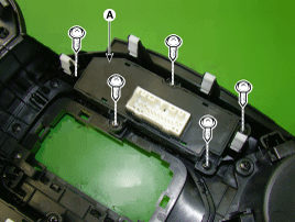
| 4. |
Remove the front tray cover (A).
[M/T]
|
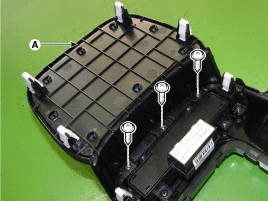
| 5. |
Remove the heater switch after loosening the screws.
|
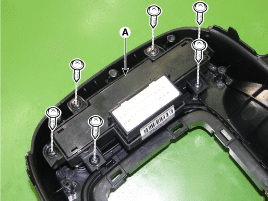
| 1. |
Disconnect the negative (-) batttery terminal.
|
| 2. |
Remove the rear door trim.
|
| 3. |
Remove the power window switch after loosen the screws
(3EA).
|
Installation
| 1. |
Install the heater switch.
|
| 2. |
Install teh floor console upper cover.
|
| 3. |
Connect the negative (-) battery terminal.
|
| 1. |
Install the power window switch.
|
| 2. |
Install the rear door trim.
|
| 3. |
Connect the negative (-) battery terminal.
|
Inspection
| 1. |
Disconnect the negative (-) batttery terminal.
|
| 2. |
Remove the floor console assembly.
|
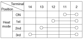
| 3. |
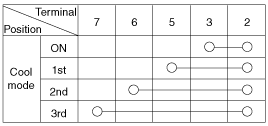
Operate driver seat heater switch and check that
continuity exists between the terminals.
If there is no continuity, replace the seat heater
switch.
|
| 1. |
Disconnect the negative (-) batttery terminal.
|
| 2. |
Remove the rear door trim.
|
| 3. |
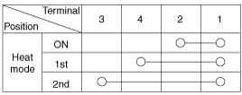
Operate driver seat heater switch and check that
continuity exists between the terminals.
If there is no continuity, replace the seat heater
switch.
|
 Seat Heater Switch. Schematic Diagrams
Circuit Diagram ...
 Air Ventilation Seat. Components
and Components Location
Air Ventilation Seat. Components
and Components Location
Components 1. Seat back blower 2. Seat cushion blower 3. Air ventilation seat control unit ...
See also:
Rear Assist Arm. Repair procedures
Removal 1. Remove the rear wheel and tire (A) from rear hub . Tightening torque : 88.2 ~ 107.8 N.m (9.0 ~ 11.0 kgf.m, 65.0 ~ 79.5 lb-ft) Be careful not to damage to the hub bolts when removing the rear ...
Repair procedures
Inspection Steering Wheel Play Inspection 1. Turn the steering wheel so that the front wheels can face straight ahead. 2. Measure the distance the steering wheel can be turned without moving the front ...
Special Service Tools
Special Service Tools Tools (Number and name) Illustration Use 09200-3N000 Engine support fixture(Beam) Removal and installation of the transaxle. Except lower supporter, use beam only with new engine ...
