 Hyundai Santa Fe: TPMS Receiver. Schematic Diagrams
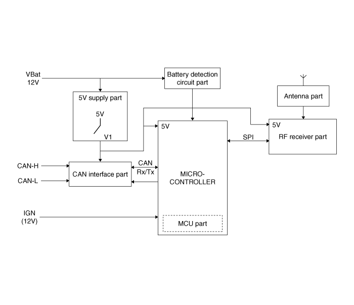
System Circuit Diagram
|
No |
Function |
|
1 |
MCU part |
|
2 |
CAN interface part |
|
3 |
5V supply part |
|
4 |
Battery detection circuit part |
|
5 |
RF receiver part |
|
6 |
Antenna part |
 TPMS Receiver. Description and Operation
Description It search automatically sensor location and learn the new sensor. To check defect of system or vehicle, use the sensor information, distance, indistinct noise, automatic learning status, vehicle ...
 TPMS Receiver. Repair procedures
Adjustment 1. Disconnect the negative (-) battery cable. 2. Remove the glove box housing. 3. Disconnect the connector. 4. Remove the bracket (B) and receiver (C) as loosen the nut (A-1ea). Tightening torque ...
See also:
Smart key immobilizer system
Your vehicle is equipped with an electronic engine immobilizer system to reduce the risk of unauthorized vehicle use. Your immobilizer system is comprised of a small transponder in the smart key and electronic ...
Floor Console Assembly. Repair procedures
Replacement [Console rear complete assembly] [M/T] • Put on gloves to protect your hands. • When prying with a flat-tip screwdriver, wrap it with protective tape, and apply protective tape around the ...
Special Service Tools
Special Service Tools Tool(Number and Name) Illustration Use Deployment tool 0957A-34100A Airbag deployment tool. Deployment adapter 0957A-3F100 Use with deployment tool. (KAB) Deployment adapter 0957A-2W100 ...
