 Hyundai Santa Fe: Valve Body. Repair procedures
Removal
| 1. |
Remove the air duct.
|
| 2. |
Remove the battery and the battery tray.
|
| 3. |
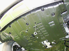
Remove the under cover(A).
|
| 4. |
Drain the coolant.
|
| 5. |
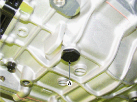
Remove the drain plug (A) and reinstall the drain plug after draining
ATF totally.
|
| 6. |
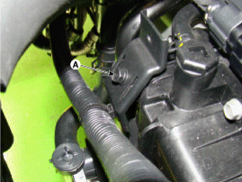
Remove the wiring bracket installation bolt (A).
|
| 7. |
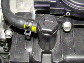
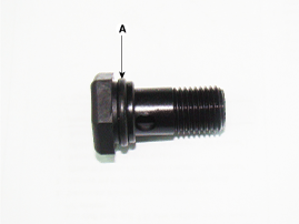
Remove the ATF Injection hole(eyebolt)(A).
|
| 8. |
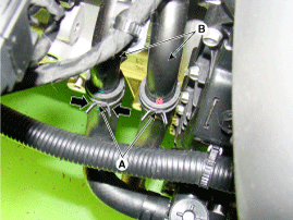
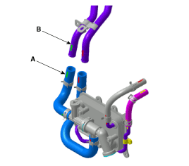
Disconnect the coolant hose (B) after removing the coolant hose
clamp (A).
|
| 9. |
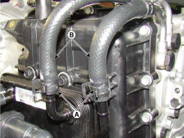
Disconnect the hose (B) after removing the automatic transaxle
fluid cooler hose clamp (A).
|
| 10. |
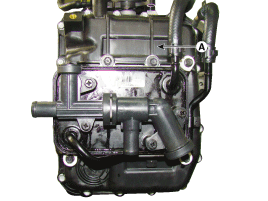
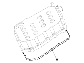
Remove the valve body cover (A).
|
| 11. |
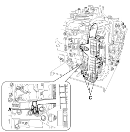
Remove the bolts (C) after disconnecting the solenoid valve connector
(B) and the oil temperature sensor connector (A).
|
| 12. |
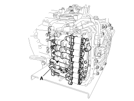
Remove the valve body assembly (A).
|
Installation
| 1. |
Installation is the reverse of removal.
|
 Valve Body. Components and Components Location
Component Location 1. Automatic transaxle 2. Valve body assembly 1. Pressure Control Valve(PCV) adjust screw 2. Solenoid valve bracket 3. Oil temperature sensor 4. Line Pressure Control Solenoid Valve ...
 ATF Warmer. Description and Operation
Description The ATF warmer is mounted on the valve body cover to reduce oil viscosity friction by increasing oil temperature under cold condition, which in turn improves fuel efficiency. It is serial mounted ...
See also:
Rail Pressure Sensor (RPS). Troubleshooting
Signal Waveform ...
Air bag - supplemental restraint system
(1) DriverŌĆÖs front air bag (2) PassengerŌĆÖs front air bag (3) Side impact air bag (4) Curtain air bag (5) DriverŌĆÖs knee air bag WARNING Even in vehicles with air bags, you and your passengers must ...
Opening the tailgate
The tailgate is locked or unlocked when all doors are locked or unlocked with the key, transmitter, smart key or central door lock switch. If unlocked, the tailgate can be opened by pressing the handle ...

