 Hyundai Santa Fe: Audio Unit. Components and Components Location
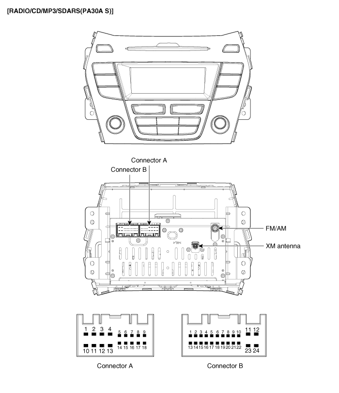
Components

Connector Pin Information
|
No. |
Connector A |
Connector B |
|
1 |
Rear left speaker (+) |
CAN High |
|
2 |
Front left speaker (+) |
TMU Audio (+) (For USA) |
|
3 |
Front right speaker (+) |
- |
|
4 |
Rear right speaker (+) |
Steering wheel remote |
|
5 |
- |
- |
|
6 |
- |
USB D (+) |
|
7 |
Ignition |
USB/iPod VDD |
|
8 |
Illumination (+) |
AUX R IN |
|
9 |
Detent |
AUX GND |
|
10 |
Rear left speaker (-) |
Mic (+) B/T |
|
11 |
Front left speaker (-) |
ACC |
|
12 |
Front right speaker (-) |
B+ |
|
13 |
Rear right speaker (-) |
CAN Low |
|
14 |
- |
TMU Audio (-) (For USA) |
|
15 |
- |
- |
|
16 |
- |
Speed |
|
17 |
Illumination (-) |
Remote GND |
|
18 |
Remote antenna |
USB D (-) |
|
19 |
|
USB/iPod GND |
|
20 |
AUX DETECT |
|
|
21 |
AUX L IN |
|
|
22 |
Mic (-) B/T |
|
|
23 |
- |
|
|
24 |
Power GND |

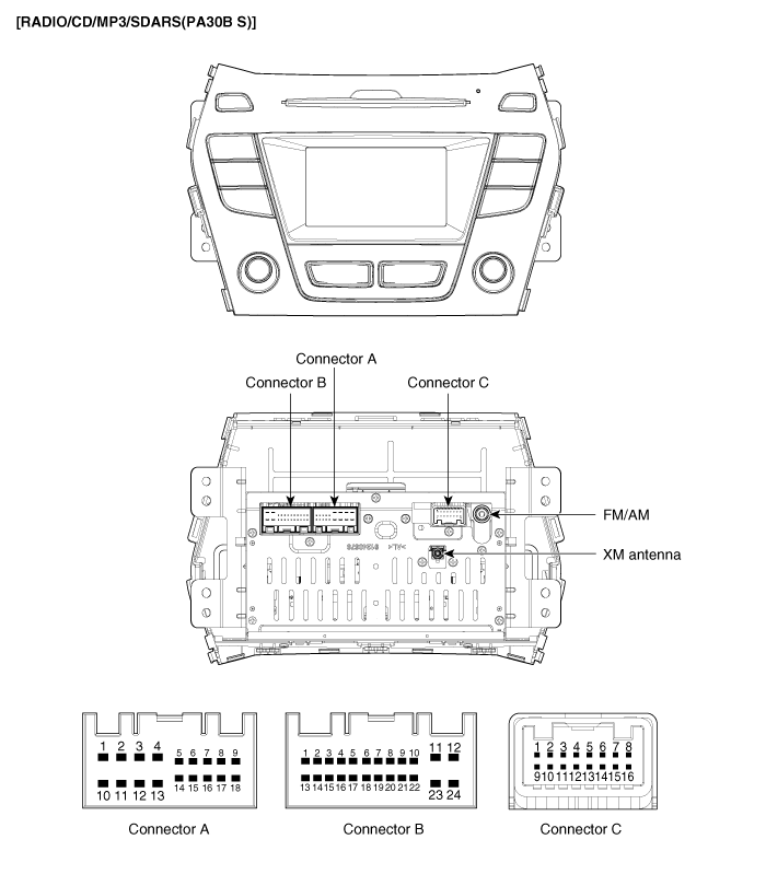
Connector Pin Information
|
No. |
Connector A |
Connector B |
Connector C |
|
1 |
Rear left speaker (+) |
CAN High |
- |
|
2 |
Front left speaker (+) |
TMU Audio (+) (For USA) |
- |
|
3 |
Front right speaker (+) |
- |
Camera ground |
|
4 |
Rear right speaker (+) |
Steering wheel remote |
Camera video input |
|
5 |
- |
- |
- |
|
6 |
- |
USB D (+) |
- |
|
7 |
Ignition |
USB/iPod VDD |
- |
|
8 |
Illumination (+) |
AUX R IN |
- |
|
9 |
Detent |
AUX GND |
- |
|
10 |
Rear left speaker (-) |
Mic (+) B/T |
Camera battery (+) |
|
11 |
Front left speaker (-) |
ACC |
Parking ground |
|
12 |
Front right speaker (-) |
B+ |
P detector |
|
13 |
Rear right speaker (-) |
CAN Low |
- |
|
14 |
- |
TMU Audio (-) (For USA) |
- |
|
15 |
- |
- |
- |
|
16 |
- |
Speed |
- |
|
17 |
Illumination (-) |
Remote GND |
|
|
18 |
Remote antenna |
USB D (-) |
|
|
19 |
|
USB/iPod GND |
|
|
20 |
AUX DETECT |
||
|
21 |
AUX L IN |
||
|
22 |
Mic (-) B/T |
||
|
23 |
- |
||
|
24 |
Power GND |
 Components and Components Location
Component Location 1. Audio unit 2. Tweeter speaker 3. Roof antenna (Radio+SDARS) 4. Front door speaker 5. Rear door speaker 6. Antenna feeder cable 7. Antenna cable connector ※ SDARS : Satellite ...
 Audio Unit. Repair procedures
Removal 1. Disconnect the negative (-) battery terminal. 2. Remove the center air vent duct (A). 3. Seperate the audio head unit (A) from crash pad after loosening the screws (4EA). 4. Remove the audio ...
See also:
Wheel replacement
When replacing the metal wheels for any reason, make sure the new wheels are equivalent to the original factory units in diameter, rim width and offset. WARNING A wheel that is not the correct size may ...
Schematic Diagrams
Circuit Diagram ...
Inhibitor Switch. Description and Operation
Description Inhibitor Switch monitors the lever's position(P, R, N, D) and is used to control gear setting signals. ...
