 Hyundai Santa Fe: Front Disc Brake. Repair procedures
Removal
| 1. |
Remove the front wheel & tire.
|
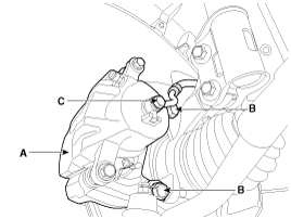
| 2. |
Loosen the hose eyebolt (C) and caliper mounting bolts (B), then
remove the front caliper assembly (A).
|
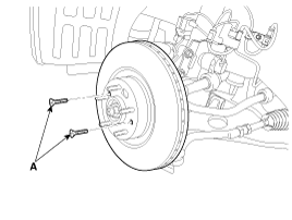
| 3. |
Remove the front brake disc by loosening the screws (A).
|
Replacement
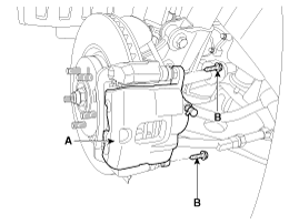
| 1. |
Loosen the guide rod bolt (B) and then remove caliper body (A).
|
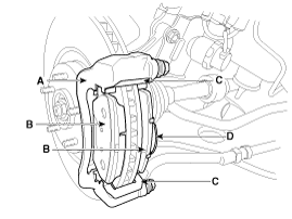
| 2. |
Replace pad shim (D), pad retainers (C) and brake pads (B) in
the caliper carrier (A).
|
Inspection
| 1. |
Check the brake pads for wear and fade.
|
| 2. |
Check the brake disc for damage and cracks.
|
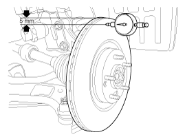
| 3. |
Remove all rust and contamination from the surface, and measure
the disc thickness at 8 points, at least, of same distance (5mm) from
the brake disc outer circle.
|
| 4. |
If wear exceeds the limit, replace the discs and pad assembly
left and right of the vehicle.
|
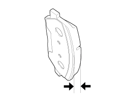
| 1. |
Check the pad wear. Measure the pad thickness and replace it,
if it is less than the specified value.
|
| 2. |
Check that grease is applied, to sliding contact points and the
pad and backing metal for damage.
|
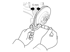
| 1. |
Place a dial gauge about 5mm (0.2 in.) from the outer circumference
of the brake disc, and measure the runout of the disc.
|
| 2. |
If the runout of the brake disc exceeds the limit specification,
replace the disc, and then measure the runout again.
|
| 3. |
If the runout does not exceed the limit specification, install
the brake disc after turning it 180° and then check the runout of the
brake disc again.
|
| 4. |
If the runout cannot be corrected by changing the position of
the brake disc, replace the brake disc.
|
Installation
| 1. |
Installation is the reverse of removal.
|
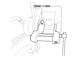
| 2. |
Use a SST (09581-11000) when installing the brake caliper assembly.
|
| 3. |
After installation, bleed the
|
 Front Disc Brake. Components and Components Location
Components 1. Guide rod bolt 2. Bleed screw 3. Caliper carrier 4. Caliper body 5. Inner pad shim 6. Brake pad 7. Pad retainer ...
 Rear Disc Brake. Components and Components Location
Components 1. Guide rod bolt 2. Bleed screw 3. Caliper carrier 4. Caliper body 5. Inner pad shim 6. Brake pad 7. Pad retainer ...
See also:
Passenger Airbag (PAB) Module. Repair procedures
Removal 1. Disconnect the battery negative cable and wait for at least three minutes before beginning work. 2. Remove the glove box housing. 3. Remove the passenger airbag mounting nuts (A). 4. Disconnect ...
Positive Crankcase Ventilation (PCV) Valve. Repair procedures
Removal 1. Disconnect the vapor hose (A). 2. Remove the PCV valve (B). Inspection 1. Insert a thin stick (A) into the PCV valve (B) from the threaded side to check that the plunger moves. If the plunger ...
Specifications
Specifications Item Specifications Transaxle type A6MF2 Engine model Gasoline 2.4GDI Torque converter type 3-element, 1-stage, 2-phase type Torque converter size Ø236 mm (9.2913 in.) ...
