 Hyundai Santa Fe: Front Hub / Knuckle / Tone Wheel. Repair procedures
Removal
| 1. |
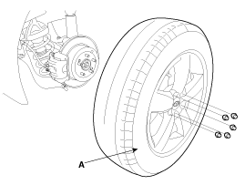
Remove the front wheel and tire (A) from front hub .
|
| 2. |
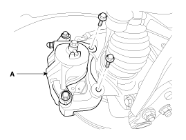
Remove the brake caliper mounting bolts, and then place the brake
caliper assembly (A) with wire.
|
| 3. |
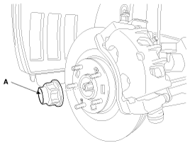
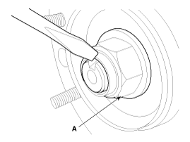
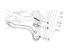
Remove the coking nut (A).
|
| 4. |
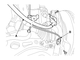
Remove the brake hose (A) and wheel speed sensor (B).
|
| 5. |
Remove the tie rod end ball joint (C) from the knuckle.
|
| 6. |
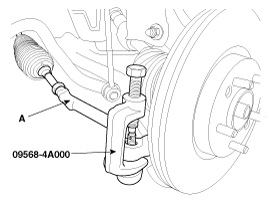
Disconnect the ball joint(A) from knuckle using the special tool
(09568-4A000).
|
| 7. |
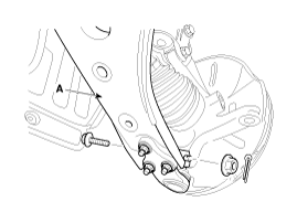
Remove the lower arm (A) mounting bolt and nut from the knuckle.
|
| 8. |
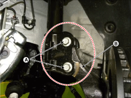
Loosen the strut mounting bolts(A) and then remove the hub and
knuckle assembly from the strut assembly (B).
|
| 9. |
Install in the reverse order of removal.
|
| 10. |
Check the front alignment.
|
Disassembly
| 1. |
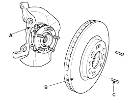
Remove the brake disc (B) from the knuckle assembly (A).
|
| 2. |
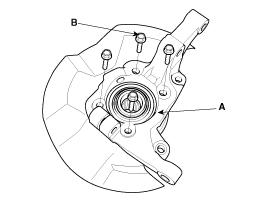
Remove the hub assembly mounting bolts (B) from the knuckle (A).
|
| 3. |
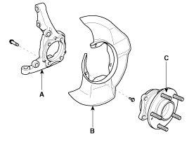
Remove the hub assembly (C) and the dust cover (B) from the knuckle
(A).
|
| 4. |
Reassembly in the reverse order of disassembly.
|
Inspection
| 1. |
Check the hub for cracks and the splines for wear.
|
| 2. |
Check the brake disc for scoring and damage.
|
| 3. |
Check the knuckle for cracks
|
| 4. |
Check the bearing for cracks or damage.
|
 Front Hub / Knuckle / Tone Wheel. Components and Components Location
Components 1. Knuckle 2. Dust cover 3. Hub assembly 4. Brake disc ...
See also:
Windows
(1) Driver’s door power window switch (2) Front passenger’s door power window switch (3) Rear door (left) power window switch (4) Rear door (right) power window switch (5) Window opening and closing ...
Luggage Room Lamp. Repair procedures
Removal 1. Disconnect the negative (-) battery terminal. 2. Remove the luggage room lamp lens (A) with a flat-tip screwdriver after loosening the screws (2EA). 3. Remove the luggage room lamp bulb (A). ...
Accelerator Position Sensor (APS). Schematic Diagrams
Circuit Diagram ...

