 Hyundai Santa Fe: Relay Box (Passenger Compartment). Repair procedures
Fuse Inspection
| 1. |
Be sure there is no play in the fuse holders, and
that the fuses are held securely.
|
| 2. |
Are the fuse capacities for each circuit correct?
|
| 3. |
Are there any blown fuses?
|
Inspection
| 1. |
The SJB can be diagnosed by using the GDS. The SJB
communicates with the GDS which then displays inputs and outputs along
with codes.
|
| 2. |
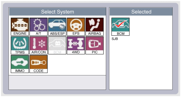
To diagnose the SJB function, select the vehicle
model, BCM and SJB.
|
| 3. |
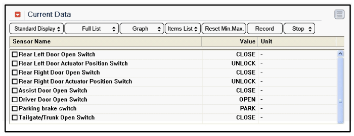
To consult the present input/out value of SJB, "Current
DATA". It provides information of SJB input/output conditions.
|
| 4. |
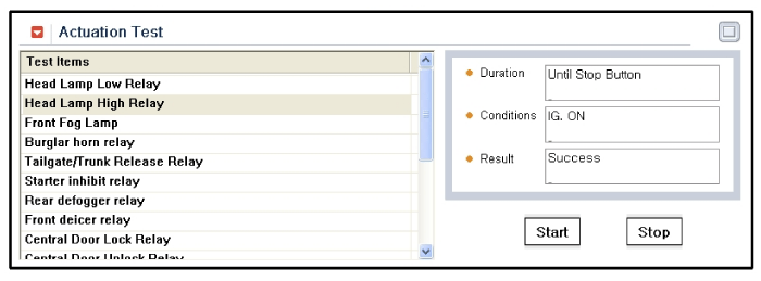
To perform functional test on SJB outputs, select
"Actuation Test"
|
Removal
| 1. |
Disconnect the negative(-) battery terminal.
|
| 2. |
Remove the crash pad lower panel.
|
| 3. |
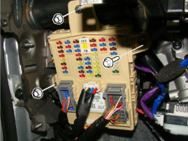
Disconnect the connectors from the fuse side of the
smart junction box.
|
| 4. |
Remove the smart junction box after loosening the
mounting nuts (2EA) and bolt.
|
| 5. |
Disconnect the connectors from the back side of the
smart junction box.
|
Installation
| 1. |
Install the smart junction box.
|
| 2. |
Install the crash pad lower panel.
|
| 3. |
Check that all system operates normally.
|
 Relay Box (Passenger Compartment). Description and Operation
Description Smart Junction Box(SJB) 1. General function : Interior Junction Box + some functions of BCM It controls loads with CAN communication and IPS. 2. Main function A. Low speed CAN communication(100 ...
See also:
Heated Oxygen Sensor (HO2S). Specifications
Specification HO2S [Bank 1/Sensor 1] Item Specification Heater Resistance (Ω) 2.5 ~ 4.0 [20°C(68°F)] HO2S [Bank 1/Sensor 2] A/F Ratio (λ) Output Voltage(V) RICH Approx. 0.9 LEAN Approx. 0.04 ...
Shift lock system
For your safety, the automatic transaxle has a shift lock system which prevents shifting the transaxle from P (Park) or N (Neutral) into R (Reverse) unless the brake pedal is depressed. To shift the transaxle ...
Headlamp, Front position lamp, Front turn signal lamp, Front fog lamp bulb replacement
(1) Headlamp (High) (2) Headlamp (Low) (3) Front position lamp (4) Front turn signal lamp/Front side marker (5) Front fog lamp (if equipped) ...


