
 Hyundai Santa Fe: Repair procedures
Removal
| 1. |
Disconnect the negative (-) battery terminal.
|
| 2. |
Remove the steering wheel.
|
| 3. |
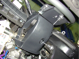
Remove the steering column upper and lower shrouds
(A) after removing 3 screws.
|
| 4. |
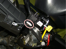
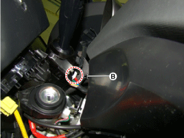
Disconnect the light switch connector (A) and the
wiper switch connector (B).
|
| 5. |
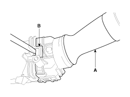
Remove the wiper switch (A) by pushing the lock pin
(B).
|

| 6. |
Remove the clock spring.
(Refer to Restraint - "Driver Airbag (DAB) Module
and Clock Spring")
|
| 7. |
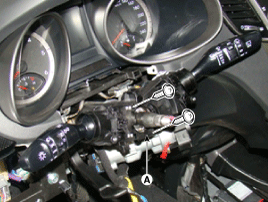
Loosen the screws (2EA) from the multifunction switch
assembly (A).
|
Installation
| 1. |
Install the multifunction switch.
|
| 2. |
Install the clock spring and steering wheel.
|
| 3. |
Install the steering column upper and lower shrouds.
|
| 4. |
Install the steering wheel.
|
Inspection
Lighting Switch Inspection
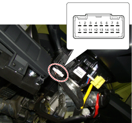
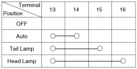
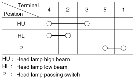
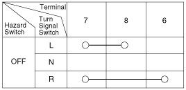
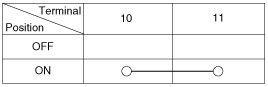
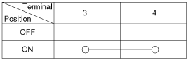
| 1. |
With the multi function switch in each position,
make sure that continuity exists between the terminals below.
If continuity is not as specified, replace the multi-function
switch
Lighting switch (Auto light)
Lighting Switch
Dimmer And Passing Switch
Turn Signal Switch
Front Fog Lamp
|

Wiper And Washer Switch Inspection
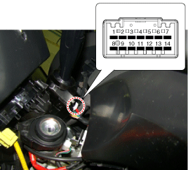
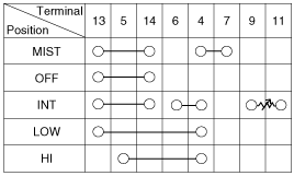
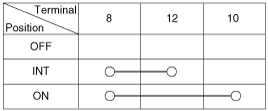
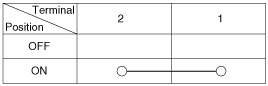
| 1. |
With the multi function switch in each position,
make sure that continuity exists between the terminals below.
If continuity is not as specified, replace the multi-function
switch.
Wiper Switch
Washer Switch
Rear Wiper Switch
Rear Washer Switch
|
Inspection (With GDS)
| 1. |
Check IPM input/output specification of multifunction
switch using the GDS. If the specification is abnormal, replace the
lamp or wiper switch.
|
| 2. |
If diagnosis is required on the multifunction switch,
select model and "IPM".
|
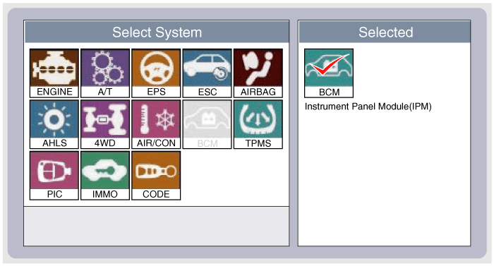
| 3. |
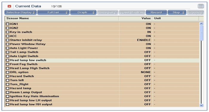
Select "Current data" and check the input/output
condition of "Multifunction switch".
|
| 4. |
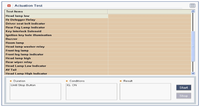
To perform test on "Multifunction switch" outputs,
select "Actuation test".
|
 Components and Components Location
Component ...
 Horn
Horn
...
See also:
Hood Assembly. Components and Components Location
Component Location 1. Hood assembly ...
SS-B Solenoid Valve(ON/OFF). Specifications
Specifications ON/OFF Solenoid Valve(SS-B) ▷ Control type : Normal low type Control pressure kpa (kgf/cm², psi) 490.33(5.0, 71.12) Internal resistance(Ω) 10~11 ...
Light ON Indicator Light
This indicator light illuminates: • When the tail lights or headlights are on. ...
