 Hyundai Santa Fe: Turn signals and lane change signals
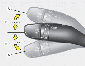
The ignition switch must be on for the turn signals to function. To turn on the turn signals, move the lever up or down (A). Green arrow indicators on the instrument panel indicate which turn signal is operating. They will self-cancel after a turn is completed. If the indicator continues to flash after a turn, manually return the lever to the OFF position.
To signal a lane change, move the turn signal lever slightly and hold it in position (B). The lever will return to the OFF position when released.
If an indicator stays on and does not flash or if it flashes abnormally, one of the turn signal bulbs may be burned out and will require replacement.
One-touch triple turn signal
To activate an one-touch triple turn signal move the turn signal lever slightly for less than 1.8 seconds and then release it. The lane change signals will blink 3 times.
You can activate or deactivate this feature. Refer to “User Settings” in this section.
✽ NOTICE
If an indicator flash is abnormally quick or slow, a bulb may be burned out or have a poor electrical connection in the circuit.
 High beam operation
To turn on the high beam headlights, push the lever away from you. Pull it back for low beams. The high beam indicator will light when the headlight high beams are switched on. To prevent the battery ...
 Front fog light
Fog lights are used to provide improved visibility when visibility is poor due to fog, rain or snow, etc. 1. Turn on the park light. 2. Turn the light switch (1) to the front fog light position. 3. To ...
See also:
Hood Weatherstrip. Repair procedures
Replacement 1. Remove the hood weatherstrip (A). • Be careful not to scratch the hood weatherstrip. 2. Install in the reverse order of removal. ...
Rear Driveshaft. Components and Components Location
Components 1. Tone wheel 2. BJ joint 3. BJ boot 4. BJ boot big part band 5. BJ boot small part band 6. Shaft 7. TJ boot small part band 8. TJ boot big part band 9. TJ boot 10. Snap ring 11. Circlip 12. ...
Rear Assist Arm. Repair procedures
Removal 1. Remove the rear wheel and tire (A) from rear hub . Tightening torque : 88.2 ~ 107.8 N.m (9.0 ~ 11.0 kgf.m, 65.0 ~ 79.5 lb-ft) Be careful not to damage to the hub bolts when removing the rear ...
