
 Hyundai Santa Fe: Front Strut Assembly. Repair procedures
Removal
| 1. |
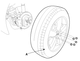
Remove the front wheel and tire (A) from front hub .
|

| 2. |
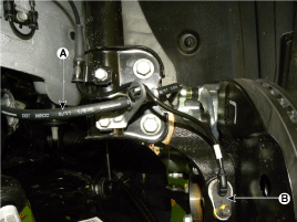
Remove the brake hose (A) & wheel speed sensor (B) from the front
strut assembly by loosening mounting bolts.
|
| 3. |
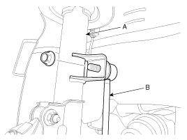
Disconnect the stabilizer link(B) with the front strut assembly(A)
after loosening the nut.
|
| 4. |
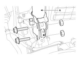
Disconnect the front strut assembly(A) with the knuckle by loosening
the bolt & nut.
|
| 5. |
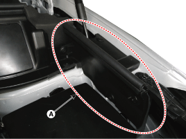
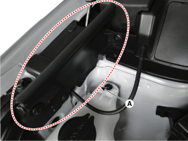
Remove the fender apron upper cover (A).
[LH]
[RH]
|
| 6. |
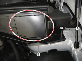
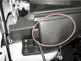
Remove the mounting retainer (A) located at the end of the cowl
top cover and the service cover (B).
[LH]
[RH]
|
| 7. |
Slightly pull the cowl top cover to your side to make a gap and
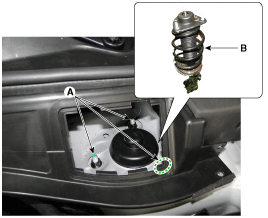
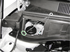
loosen the strut mounting nuts (A-3ea).
|
| 8. |
Remove the strut assembly (B).
[LH]
[RH]
|
| 9. |
Install in the reverse order of removal.
|
| 10. |
Check the front alignment.
|
Disassembly
| 1. |
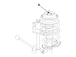
Remove the dust cover(A).
|
| 2. |
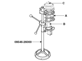
Using the special tool (09546-26000), compress the coil spring
(A).
|
| 3. |
Remove the self-locking nut (C) from the strut assembly(B).
|
| 4. |
Remove the insulator, spring seat, coil spring and dust cover
from the strut assembly.
|
Inspection
| 1. |
Check the strut insulator for wear or damage.
|
| 2. |
Check rubber parts for damage or deterioration.
|
| 3. |
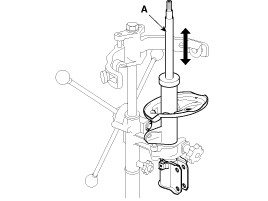
Compress and extend the piston rod (A) and check that there is
no abnormal resistance or unusual sound during operation.
|
Disposal
| 1. |
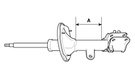
Fully extend the piston rod.
|
| 2. |
Drill a hole on the A section to remove gas from the cylinder.
|
Reassembly
| 1. |
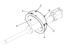
Install the spring lower pad (D) so that the protrusions(A) fit
in the holes (C) in the spring lower seat (B).
|
| 2. |
Compress coil spring using special tool (09546-26000). Install
compressed coil spring into shock absorber.
|

| 3. |
After fully extending the piston rod, install the spring upper
seat and insulator assembly.
|
| 4. |
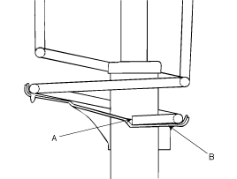
After seating the upper and lower ends of the coil spring (A)
in the upper and lower spring seat grooves (B) correctly, tighten new
self-locking nut temporarily.
|
| 5. |
Remove the special tool (09546-26000).
|
| 6. |
Tighten the self-locking nut to the specified torque.
|
 Front Strut Assembly. Components and Components Location
Components 1. Strut assembly 2. Insulator 3. Bearing 4. Spring upper pad 5. Spring 6. Dust cover 7. Spring lower pad ...
 Front Lower Arm. Repair procedures
Removal 1. Remove the front wheel and tire (A) from front hub . Tightening torque: 88.2 ~ 107.8 N.m (9.0 ~ 11.0 kgf.m, 65.0 ~ 79.5 lb-ft) Be careful not to damage to the hub bolts when removing the front ...
See also:
Front Door Outside Handle. Components and Components Location
Component Location 1. Front door outside handle ...
Cup holder
Front Rear Cups or small beverage cans may be placed in the cup holders. To use the center cup holder, pull down the armrest and press the open button. WARNING - Hot liquids Do not place uncovered cups ...
Description and Operation
Description The 6-speed automatic transaxle consists of an overdrive clutch (OD/C), a one-way clutch (OWC), a lower and reverse brake (LR/B), an underdrive brake (UD/B), a 26 brake (26/B), and a 35R clutch ...
