
 Hyundai Santa Fe: Purge Control Solenoid Valve (PCSV). Repair procedures
Inspection
| 1. |
Turn the ignition switch OFF.
|
| 2. |
Disconnect the PCSV connector.
|
| 3. |
Measure resistance between the PCSV terminals 1 and 2.
|
| 4. |
Check that the resistance is within the specification.
|
Removal
| 1. |
Turn the ignition switch OFF and disconnect the battery negative
(-) cable.
|
| 2. |
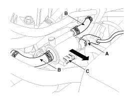
Disconnect the purge control solenoid valve connector (A).
|
| 3. |
Disconnect the vapor hoses (B) from the purge control solenoid
valve.
|
| 4. |
Remove the valve from the bracket (C) in the direction of the
arrow.
|
Installation
|

|
| 1. |
Install in the reverse order of removal.
|
 Purge Control Solenoid Valve (PCSV). Schematic Diagrams
Circuit Diagram ...
 CVVT Oil Control Valve (OCV). Description and Operation
Description Continuous Variable Valve Timing (CVVT) system advances or retards the valve timing of the intake and exhaust valve in accordance with the ECM control signal which is calculated by the engine ...
See also:
Smooth cornering
Avoid braking or gear changing in corners, especially when roads are wet. Ideally, corners should always be taken under gentle acceleration. If you follow these suggestions, tire wear will be held to ...
Overhead Console Lamp. Repair procedures
Inspection 1. Remove the overhead console lamp assembly then check for continuity between terminals. If the continuity is not as specified, replace the map lamp switch. [General] [Panorama Sunroof] Removal ...
Overdrive Clutch Control Solenoid Valve(OD/C_VFS). Repair procedures
Inspection 1. Turn ignition switch OFF. 2. Remove the air duct. 3. Disconnect the solenoid valve connector(A). 4. Measure resistance between sensor signal terminal and sensor ground terminal. 5. Check ...
