Description
Body Control Module Controls The Followings
| - |
Door lock/unlock Control
|
| - |
UMS(User Mode Setting) Control
|
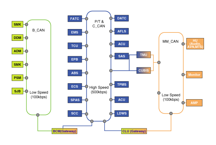
Communication Network Diagram

Abbreviation
|
Explanation
|
C_CAN
|
Chassis Controller Area Network
|
B_CAN
|
Body Controller Area Network
|
MM_CAN
|
Multi media Controller Area Network
|
SMK
|
Smart Key ECU
|
DDM
|
Driver Door Module
|
ADM
|
Assist Door Module
|
PSM
|
Power Seat Module
|
SJB
|
Smart Junction Box
|
ESC
|
Electronic Stabilty Control
|
SPAS
|
Smart Parking Assist System
|
SWRC
|
Steering Wheel Remote Controller
|
PCU
|
Power-train Control Unit
|
ECU
|
Engine Control Unit
|
TCU
|
Transmission Control Unit
|
EPB
|
Electronic Parking Brake
|
ABS
|
Anti-lock Brake System
|
BCM
|
Body Control Module
|
SCC
|
Smart Cruise Control
|
DATC
|
Dual Automatic Temp Control
|
MDPS
|
Motor Driven Power Steering
|
SAS
|
Steering Angle Sensor
|
TPMS
|
Tire Pressure Monitoring System
|
ACU
|
Airbag Control Unit
|
CLU
|
Cluster
|
HU
|
Head Unit (Audio, AVN, MTS)
|
Function
|
1. |
Wiper & Washer Control
| A. |
Front wiper MIST Control Function
|
| B. |
Front wiper INT Control Function
|
| C. |
Front wiper washer Control Function
|
| D. |
Front wiper low/high Control Function
|
| E. |
Head lamp washer Control Function
|
| F. |
Rear wiper low Control Function
|
| G. |
Rear wiper INT Control Function
|
| H. |
Rear wiper washer Control Function
|
|
|
2. |
Defroster Control
| A. |
Rear defogger Control Function
|
| B. |
Front deicer control Function
|
|
|
3. |
Driving Control
| A. |
Key interlock solenoid Control Function
|
| B. |
ATM solenoid Control Function
|
|
|
4. |
Tailgate Control
| A. |
Tailgate open Control Function
|
|
|
5. |
Window Control
| A. |
Power window main timer Control Function
|
| B. |
Safety power window Control Function
|
| C. |
Seat bel reminder Control Function
|
| D. |
Key reminder(Key operated warning) Control
Function
|
| E. |
Parking brake Control Function
|
| F. |
RKE key teaching Control Function
|
| G. |
SMK system warning Control Function
|
| H. |
Alarm horn Control Function
|
| I. |
Sunroof open warning Control Function
|
| J. |
Rear area parking assist system Control Function
|
|
|
6. |
Interior Control
| A. |
Room lamp Control Function
|
| B. |
Key hole illumination Control Function
|
|
|
7. |
Exterior Control
| A. |
Tail lamp Control Function
|
| B. |
Head lamp DRL Control Function
|
| C. |
Head lamp high Control Function
|
| D. |
Head lamp welcome Control Function
|
| E. |
Escort Control Function
|
| F. |
Auto light Control Function
|
| H. |
Front fog Control Function
|
| I. |
AV tail Control Function
|
|
|
10. |
Flasher output Control
| A. |
Alarm flashing Control Function
|
| B. |
Arm/Disarm flashing Control Function
|
| C. |
Panic flashing Control Function
|
| D. |
MTS flashing Control Function
|
| E. |
Tailgate open/close flashing Control Function
|
| F. |
Two turn unlock set/reset flashing Control
Function
|
| G. |
Crash unlock flashing Control Function
|
| H. |
Remote start flashing Control Function
|
|
|
11. |
Door lock/unlock Control
| A. |
Central door lock/unlock Control Function
|
| B. |
Mechanical door lock/unlock Control Function
|
| C. |
Two turn unlock Control Function
|
| D. |
SMK door lock/unlock Control Function
|
| E. |
RKE door lock/unlock Control Function
|
| F. |
MTS door unlock Control Function
|
| G. |
ATWS relcok Control Function
|
| H. |
Auto door lock/unlock Control Function
|
| I. |
Crash unlock Control Function
|
| J. |
Key reminder unlock Control Function
|
|
|
12. |
Burglar alarm Control
|
Removal 1. Disconnect the negative (-) battery terminal. 2. Remove the crash pad center panel. 3. Disconnect the body control module connectors (A). 4. Remove the body control module (A) after loosening ...
See also:
Anti-lock brake system (ABS)
WARNING ABS (or ESC) will not prevent accidents due to improper or dangerous driving maneuvers. Even though vehicle control is improved during emergency braking, always maintain a safe distance between ...
Air ventilation seat
The Air ventilation seat is provided to cool the front seats during hot weather by blowing air through small vent holes on the surface of the seats. While the engine is running, press the cooling portion ...
Power Window Switch. Components and
Components Location
Components Driver Power Window Switch Assist Power Window Switch Rear Power Window Switch ...
 Hyundai Santa Fe: Description and Operation
 Schematic Diagrams
 Repair procedures